Risk Analysis and Basic Screening
Use SnRD to identify Squeak and Rattle issues.
Risk Analysis & Basic Screening use case describes the basic screening analysis that the S&R analyst would perform. Starting from a NVH FE-model, built for other purposes, the analyst wants to define a first set of E-lines to assess the S&R performance of a system. Typically, this first analysis will occur at the early stage of the virtual development process, thus a lack of input might be a road blocker for the S&R CAE engineer. Therefore, the SnRD simple process will close this gap by offering automation and a set of default settings enabling this first analysis.
- Interface to be analyzed
- Dimensions and properties
- Loading Conditions
- Create FE model prepared for analyzing Squeak and Rattle
- Create Rattle E-Lines using Auto method.
- A SineSweep loadcase, with user settings.
- Run analysis, create summary page and export PPT report.
- Clean FE model- no SnRD information.
%20Analysis%20-%20Basic-Quick.png) Figure 1.
Figure 1. - Import tutorial model
- Define Interfaces.
- Create Evaluation Lines at interfaces.
- Create SineSweep based Dynamic event and export solver deck.
- Solve the
.FEMsolver deck to obtain results and files.
- Solve the
- Use the solver deck, E-Lines definition file and to post
process results.
- Generate histograms, contour plots, etc.
- Generate PPT report HyperWorks Report tool.
Files Required
Files required to complete the usecase.
Step 1: Import Model
Below are the steps to import files model, DTS and material files:
-
Click Import.
This will import the selected model to the session.
 Figure 2.
Step 2: Define the Interface Between Components by Creating Geometric Lines
Create geometric lines which will be used to define the interfaces to evaluate.
Create Geometric Lines
Use Create Geometric Lines tool to create geom lines in the model.
-
In the HyperWorks toolbar, from
View
 option, select
QuickReviewComps.
option, select
QuickReviewComps.
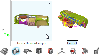 Figure 3. This isolates only the components which are needed for squeak and rattle assessment.
 -
From Setup group, select Define
Interface.
 Figure 4. A guide bar will appear.
 -
Click
 to open advanced options.
 Figure 5.
 -
Click
 .
This will create the geometric lines at the component edges in the model.
.
This will create the geometric lines at the component edges in the model.
Step 3: Create E-Lines
Create and Manage all the E-Lines in the model.
Create E-Lines
-
From Setup group, select Create
E-Line tool.
 Figure 6. A guide bar will appear.
 -
Click .
This creates 11 E-Lines in the model.
 Figure 7.
Realize All E-Lines
-
From Setup group, select Manage
E-Line.
 Figure 8. A guide bar will appear.
 -
Click
 .
A user message will appear. Click Yes.
.
A user message will appear. Click Yes. Figure 9. This realizes all the E-Lines in the model.
 Figure 10.
Manage E-Lines
-
From Setup group, select .
 Figure 11. Review E-Lines table will appear.
 Figure 12.
 -
Optional: Scan through E-lines and delete possible
duplicates.
-
Click
 .
A user message appears. Click Yes to delete selected lines.
.
A user message appears. Click Yes to delete selected lines. Figure 13.
-
Click
Step 4: SineSweep Loadcase Setup and Export OptiStruct File
Setup a SineSweep Loadcase and export the solver file. Solve the file using OptiStruct to obtain output files.
SineSweep Loadcase Setup
-
From Setup group, select Dynamic
Event.
 Figure 14. A guide bar will appear.
 -
Click to view advanced options. Define
4 as the input value for Output
Frequency under Time Step option.
Accept other default values.
 Figure 15.
 -
From the graphics area, select the node shown in the below image.
 Figure 16. A microdialog will appear.
 Figure 17.
 -
Click .
This creates the SineSweep loadcase with the load collectors and other entities required for the simulation. You can view the model browser for the new entities that are created.
Export OptiStruct Solver File
-
From Analyze group, select Export
OptiStruct Solver File.
 Figure 18.
 -
Model Export window will appear.
 Figure 19.
.FEM solver deck
to solve on OptiStruct solver. Once done, two output files are generated:
.H3D and .PCH. These files will be used in
the Post Processing of results.Step 5: Risk Assessment
Evaluate risks for Squeak and Rattle with the Risk Assessment tool.
-
Open Risk Assessment tool.
 Figure 20.
 -
Click Plot.
Relative Displacement plot for the E-Lines are plotted in the HyperView window.
 Figure 21.
Step 6: Generate Summary Report
Export a Squeak and Rattle summary report using HyperWorks Report tool.
-
In the active HyperWorks session, click
Report.
This launches the Report ribbon..
 Figure 22.
 -
Click Capture .
 Figure 23. Select Capture Session from the Add Module window. This launches the Report tab and the report module is added in the tree.
 -
Click Export.
 Figure 24. This will execute the module and generate outputs. A file browser window will appear.
 -
Enter SnR Risk Summary Report in the File
Name and click Save.
This generates the document report and will launch automatically.
 Figure 25.