Add/Edit Motion Contacts
Create or edit motion contacts between parts or sets of parts.
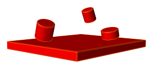 Figure 1. Example 1: All parts are placed in the red set.
 |
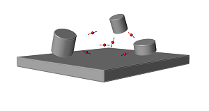 Figure 2. Example 1: Contacts are created between every
possible combination of parts in the red set. (The image
below shows what you see when the Individualize option
is selected.)
 |
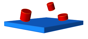 Figure 3. Example 2: Parts are placed into both the red and
blue sets.
 |
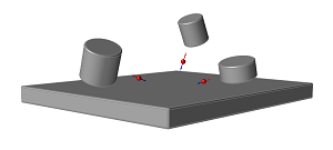 Figure 4. Example 2: Contacts are not created between parts in
the same set, but are established between parts in the
different sets.
 |
- Refer to Best Practices for Motion Contacts for additional guidance when applying motion contacts to your model.
- The plotting feature for motion contacts is only available if they have been individualized.
- When using the At Free Joints option, hold the Ctrl key while clicking Create on the guide bar to automatically navigate to the next possible contact pair. This allows you to create motion contacts at free joints very quickly.
- When using the At Cylinders and Holes option, Inspire will automatically detect Cylinder and Hole candidate pairs. During creation, the guide bar arrows let you navigate through the detected pairs so you can 1) accept the selections in the contact sets, 2) Ctrl + left click on features to add/remove them from the contacts sets, or 3) navigate through individual features for the currently active contact set by holding down Ctrl while clicking the guide bar arrows.
- Hold Ctrl while clicking the Motion Contacts icon on the ribbon to enter editing mode. This will edit the most recent contact that was created. To edit multiple contacts simultaneously, select multiple contacts in the Model Browser before selecting the Motion Contacts tool.
- You can visualize your motion contact forces using the Force Explorer.
- Suppress/Unsuppress a motion contact to understand its effect on your model. On the contact, right-click and select Suppress. From the Model Browser or Table, right-click and select Unsuppress.
Find Options
Click the ![]() menu on the guide bar to apply global
options before creating motion contacts.
menu on the guide bar to apply global
options before creating motion contacts.
- Enable Friction
- Enable this option to include forces that arise from frictional effects.
- Collision Type
- Select a collision type - Impact (default), Poisson, or Volume.
- Force Computed At
- Select whether the contact normal force is applied at the nodes or the element center when parts come into contact.
- Exclude Design Spaces
- Enable this option to prevent design spaces from being selectable.
- Exclude Ground
- Enable this option to prevent ground parts from being selectable.
- Exclude Skewed Holes
- Enable this option to prevent skewed holds from being selectable.
Microdialog Options
Use the options in the microdialog to edit the motion contact.
| Option | Description | |
|---|---|---|
| Enable Friction | Enable this option to include forces that arise from frictional
effects. Click the
|
|
| Collision Type Select a collision type for the normal force
calculation. Click the |
Impact (default) |
|
| Poisson |
|
|
| Volume |
|
|
| Force Computed At |
|
|
| Reset |
|
|
Motion Contact Properties
Use the following properties in the Property Editor to refine motion contacts.
- Precise Contact Event
- If you enable this property and enter a tolerance, the solver will more precisely determine when two parts come into contact. Enabling this option will improve the accuracy and robustness of motion contact simulations, but will also increase simulation time, so it should be used only when necessary.
- Refine Step Size
- If you enable this property and enter a new step size, the solver will use it as the maximum step size for the simulation after the contact is detected.
- Keep Force Results
-
This option allows you to limit the number of contact forces that are stored in the model after motion analysis. The choices for an individual motion contact are: Default, All, Region Only, and None.
- Default: This setting uses the option selected on the Motion Analysis Settings window under Contacts. (This is a global setting, whereas the options set in the Property Editor apply to individual motion contacts.)
- All: Select this option to include both the individual forces and the summed contact forces.
- Region Only: This option excludes individual forces and gives you forces that have been summed at their respective contact regions. Region only forces correspond to the Sum Forces: At contact region option on the Force Explorer.
- None: Select this option to keep no force results for the selected motion contact. This helps to reduce the size of the .stmod file because you are storing less data.
If you choose Region Only or None, be aware that when animating motion results with the Force Explorer, you will only see the level of content you specified for a given contact. For example, if you choose Region Only you will not see the individual (unsummed) force vectors. Likewise, you would not see any of the force vectors due to contact if you select None.
Motion Contacts Table
The Motion Contacts table lists all of the motion contacts in your model including the parts in each contact set and various other parameters.
Location: Motion Contacts tool, satellite icon ![]()
 Figure 5. Motion Contacts Table
| To | Do this |
|---|---|
| Rename a motion contact | Select the cell in the table and then click again to make the field editable. |
| Change the collision type | Select the cell in the table and then select a different option from the list. |
| Edit a parameter | Select the cell in the table and then click again to make the field editable. |
| Sort a column | Click the column header. Click repeatedly to toggle between ascending and descending order. |
| Add or remove columns | Right-click on a column header. |
Analytical vs Mesh-Based Contacts
If motion contact sets contain parts that are detected as box primitives, the solution between the box and other analytical shapes (sphere, cylinder, and frustum) is analytical rather than mesh based. Using geometric primitives in these cases generally improves the efficiency of the solution. The following table shows when an analytical vs. mesh-based solution is used:
| SPHERE | BOX | ELLIPSOID | CYLINDER | FRUSTUM | MESH | |
|---|---|---|---|---|---|---|
| SPHERE | Analytical | Analytical | Analytical | Analytical | Analytical | Semi |
| BOX | Mesh | Mesh | Analytical | Analytical | Mesh | |
| ELLIPSOID | Mesh | Mesh | Mesh | Mesh | ||
| CYLINDER | Analytical | Analytical | Mesh | |||
| FRUSTUM | Analytical | Mesh | ||||
| MESH | Mesh |
When using the analytical method, each of the contacting geometries is represented by an analytical expression, whereas with the mesh method both geometries are tessellated. Semi indicates that one of the geometries is represented analytically, while the other is tessellated.
Shortcuts
| To | Do this |
|---|---|
| Select/deselect part | Click |
| Advance from the first set to the second step | Right-click |
| Create contact | Right-click (both sets must be populated) |
| Advance from one part pair to the next | When using the At Free Joints option, use the arrow keys on the guide bar to quickly navigate from one part pair to the next. Hold Ctrl while clicking Create on the guide bar to quickly create and advance to the next pair. |
| Edit a contact | Hold Ctrl while clicking the Motion Contacts icon on the ribbon. |
| Edit multiple contacts | Select multiple contacts in the Model Browser, then click the Motion Contacts icon on the ribbon. |
| Exit the tool | Right-click and mouse through the check mark to exit, or double-right-click. |
 button on the guide bar.