Torsion Springs
Use the Add/Edit Torsion Springs tool to apply a rotational spring-damper force about the pivot axis for two parts.
Location: Motion ribbon, Forces group, Springs icon
Click the ![]() satellite icon that appears when you hover over the Springs icon to view
a list of all coil springs or torsion springs in your model.
satellite icon that appears when you hover over the Springs icon to view
a list of all coil springs or torsion springs in your model.
Add/Edit Torsion Springs
Position the torsion spring, then define the preload torque, torsional stiffness, and torsional damping rates.
-
Select the Add/Edit Torsion Springs tool on the Springs
icon.

-
Enter the torsional stiffness (KT) and torsional damping (CT) rates, or enter
zeros to disable them.
- If you want a damper rather than a spring, change the spring Type in the microdialog and select Damper.
- Color attributes for the spring can be set using the Property Editor.
- Suppress/Unsuppress a torsion spring to understand its effect on your model. On the spring, right-click and select Suppress. From the Model Browser or Table, right-click and select Unsuppress.
Nonlinear Spring Dampers
Nonlinear stiffness and damping characteristics can be entered for spring dampers for motion analysis.
-
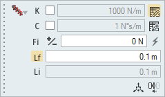
For a nonlinear spring damper, deselect the check boxes for the spring
stiffness (K) and damping (C) rates as desired.
-
Click the table icon to open the Profile Editor. (The stiffness curve example
below is for a coil spring. Similar profiles are available for dampers and
torsion springs.)
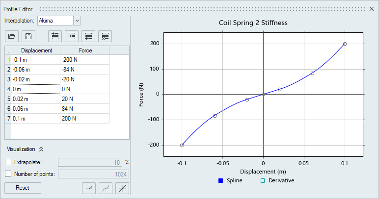
Figure 1. Example of a Coil Spring Stiffness Curve -
Edit the data in the table, or use the
 buttons to remove or reflect the curve as
desired.
buttons to remove or reflect the curve as
desired.
- Sometimes it is easier to remove the left side data, work on the right side data, and then use the Reflect to Left Side button to reflect your data.
- Clicking the Replace with Linear Equivalent button will use the Stiffness value (shown greyed out on the microdialog) and display it as an editable curve in the graphical area of the Profile Editor.
- The Derivative button in the legend is helpful for the Akima and Cubic interpolation methods because it helps you visualize discontinuities in your data. Introducing more points may help you smooth the profile.
- The Provide Signals to Plant option is available for spring dampers in motion, but is disabled by default. It can be found in the Property Editor and when enabled, the motion Export operation will include the necessary plant signals in the .mdl file for use in MotionView, MotionSolve, and Altair Activate.
- See the Profile Editor for an explanation of the buttons and visualization options.
Microdialog Options
Use the options in the primary microdialog to edit the behavior of a torsion spring.
Click the ![]() to view advanced
options.
to view advanced
options.
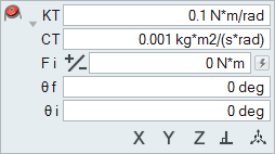
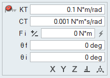
Figure 2. Torsion Springs Microdialog
- Type
- The default type is spring damper. You can also select just the spring, or just the damper. It is advisable to include some damping.
- Set Torsional Stiffness
- Enter a positive value for the torsional stiffness rate of the spring. (To have no torsional stiffness, set the spring Type to Damper.)
- Set Torsional Damping
- Enter a positive value for the torsional damping rate of the spring.
- Reverse Preload Torque
- Reverse the direction of the preload torque in the spring.
- Set Preload Torque
- Enter a magnitude for the preload torque in the spring.
- Set Free Angle (θ f)
- The free angle is the angle of the spring in its resting state. If you enter a preload torque, the free angle is automatically calculated from the torsional stiffness.
- Installed Angle (θ i)
- The angle of the spring as installed in the mechanism.
- Flip to the Other Side
- Flip the torsion spring to the other end of the hole or pin. This only changes the appearance of the spring.
- Align to Global X, Y, or Z Axis
- Align the pivot axis to the global X, Y, or Z direction. Not applicable for holes or pins.
- Align Normal to Face
- Align the pivot axis to be perpendicular to the first surface. Not applicable for holes or pins.
- Move Torsion Spring
- Open the Move tool to place the spring at a distance. Not applicable for holes or pins.
Torsion Spring Properties
Refine the behavior and appearance of torsion springs using the properties available in the Property Editor (F3)
- Restrain Centerline
- When enabled, the pivot axis of the torsion spring is restrained to essentially create a cylindrical joint between the parts.
Springs Table
The Springs table lists all of the coil and torsion springs in your model and allows you to edit various attributes. Click the Torsion tab to view torsion springs.
Location: Springs tool, satellite icon ![]()
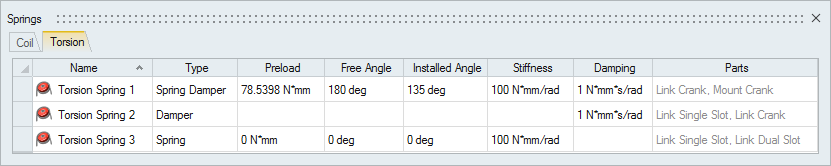
Figure 3. Springs Table
| To | Do this |
|---|---|
| Rename a spring | Select the cell in the table and then click again to make the field editable. |
| Change a value | Select the cell in the table and then click again to make the field editable. Some fields are for display only. |
| Sort a column | Click the column header. Click repeatedly to toggle between ascending and descending order. |
| Add or remove columns | Right-click on a column header. |
Shortcuts
| To | Do this |
|---|---|
| Deselect a feature | Hold down the Ctrl key and left-click a selected (red) feature. |
| Exit the tool | Right-click and mouse through the check mark to exit, or double-right-click. |