FDMA (Broadcast)
Broadcasting networks (TV, radio or paging networks) are only using downlink signals radiated from fixed terrestrial transmitters or satellites to fixed or mobile receivers. Accurate propagation models allow a detailed analysis of the coverage scenario and avoid areas without any coverage.
Air Interface Parameters
All parameters related with a selected air interface can be specified on the Air Interface tab of the Edit Project Parameter dialog.
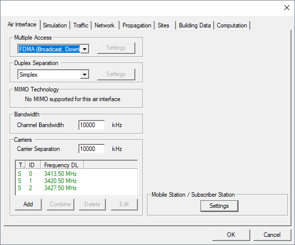
Figure 1. The Edit Project Parameters dialog, Air interface tab.
For frequency division multiple access in broadcast mode, the following settings are available:
- Duplex Separation
- As this multiple access scheme is designed for broadcasting systems (transmission in downlink only), the duplex separation is fixed to simplex.
- Channel Bandwidth
- Available bandwidth of the channel. This value is used to calculate thermal noise impact.
- Carrier Separation
- Available bandwidth of the channel. This value is used to calculate thermal noise impact.
- Mobile Station /Subscriber Station
- Receiver of Mobile Station
- Noise figure of receiver (Parameter defines the additional noise generated due to the receiver within the mobile station).
- Minimum SNIR which is required to receive the signals.
- Minimum required signal level required for reception.
- General Parameters of Mobile Station
- Antenna gain of the mobile station.
- General losses (for example, body). General parameter, which can be used to model all kind of additional losses (body losses) around a mobile station.
- Fast fading
- The parameter Fast Fading Margin represents the difference (in dB) between the maximum possible transmitting power and the maximum allowed transmitting power. to ensure the fast power control to compensate the deep fades of the radio channel this specific headroom is required. Appropriate values for this headroom have to be determined via link level simulations and will depend on the mobile speed.
- Receiver of Mobile Station
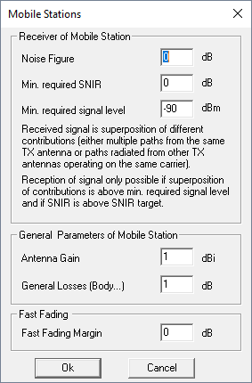
Figure 2. The Mobile Stations dialog.
Output Options
- General Results
- Best Server (Cell Assignment)
- EMC Analysis
- Results Based on the Analysis of the Downlink
- Maximum Received Power in Downlink (at MS)
- SNIR for each Carrier at MS
- Superposition of Identical Carriers
- Number of Carriers Received
- Number of TRX Received
- Number of Sites Received