Fix Geometry

Identify geometry issues, clean up invalid geometry, collapse tiny edges and tiny faces, and remove spikes.

Collapse Tiny Edges and Faces

Identify and collapse tiny edges and faces.

  1. Click a PolyNURBS object.
  2. Choose from the following options:
    • To remove tiny edges, press S.
    • To remove tiny faces, press D.
  3. (Optional) To redefine just how short the tiny edges or small the tiny faces have to be in order to be detected by Inspire Studio, adjust the Tiny Threshold.
  4. In the Edit PolyNURBS tool panel, click Select Tiny.
  5. Right-click to collapse the tiny edges or faces.
    Note: Do not use Delete on tiny edges or faces, as this could produce distorted geometry.
Tiny edges or faces will be collapsed into a single vertex.

Identify Geometry Issues

Identify geometry issues, especially when working with imported polygonal models.
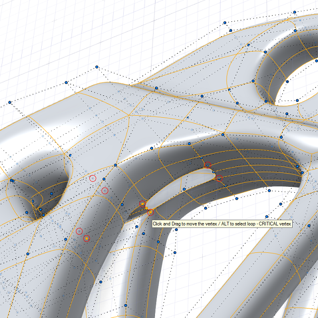
  1. Check the modeling window:
    • Nonmanifold vertices are circled in red and nonmanifold edges are shown as dotted red lines. They contribute to an open geometry (not watertight).
    • Critical vertices are circled in red. To see critical vertices, you may need to press N to turn on Nurbify. They produce "bad geometry" such as gaps when the object is Nurbified.
    Tip: If a vertex is circled in red, hover over it. The tooltip tells you if the vertex is nonmanifold or critical.
  2. Press A, S, or D to open the Edit PolyNURBS tool panel. At the bottom, under PolyNURBS Info and Additional Info, you can find the following information:
    • The number of nonmanifold vertices, nonmanifold edges, critical vertices, tiny edges, and tiny faces are displayed in red. Inspire Studio automatically detects tiny edges and tiny faces. They are too small to see with the naked eye, but may correspond to invalid geometry.
    • If the number of boundary edges is 0, the PolyNURBS is a closed solid. It is also useful to check the number of boundary edges when you want to bridge the boundary edges to another set of edges.


If you identify tiny edges and tiny faces that correspond to invalid geometry, you can collapse them.

Remove Spikes

Remove spikes, which occur when there are duplicate vertices or a gap between vertices.

  1. Find the problem area.
  2. Choose one of the following options:
    • Select the duplicate vertices. In the Edit PolyNURBS tool panel, click the Weld Selected button.
    • Select all vertices. In the Edit PolyNURBS tool panel, specify the Tolerance and click the Weld Selected Tolerance button. All vertices within the specified tolerance value will be welded.

Display Open Edges in Red

If an object is not a closed solid, you can use one of these tools to display open edges in red.

  1. On the Analysis ribbon, click the Area/Volume tool.

  2. In the modeling window, click the object that is not a closed solid.
  3. In the Area/Volume tool panel, under Display, select Surf. open edges.


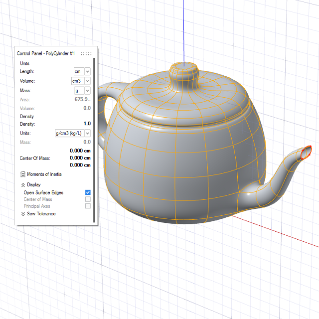
    Note: The Sew Tolerance is used to determine whether the objects form a solid. To change the sew tolerance, enter a Custom tool (tolerance). The default is 0.005.
  4. Right-click and mouse through the check mark to exit, or double-right-click.
  5. On the analysis ribbon, click the Tolerance check tool.


  6. In the modeling window, click the object that is not a closed solid. The control panel displays the number of open edges.
  7. In the control panel, edit the tolerance as required. A lower value displays smaller gaps.
  8. Right click and mouse through the check mark to exit, or double right click.


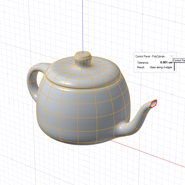
Note: The Tolerance Tool Check can also be used to check for open edges. If you select an object that is not a closed solid, the Tolerance Check will display the number of open edges in the Control Panel.