Symmetry
Define the symmetry boundary conditions. You can define up to two symmetry planes. The second symmetry plane must be parallel or orthogonal to the first.
-
Click the Part icon.
-
Click the Symmetry icon.
A blue arrow is displayed with an origin point.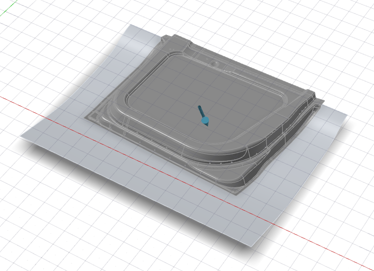
-
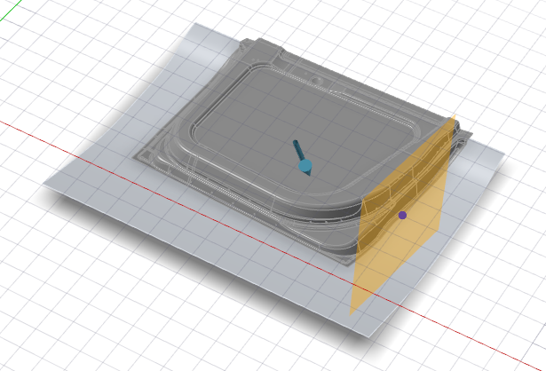
Hover over a part to position the symmetry plane, and then click to create the
symmetric copy.
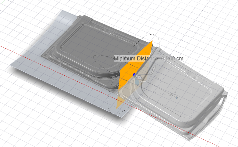
Note: To add a gap between the original part and the symmetric copy, change the Minimum Distance by dragging the yellow arrow or entering a value.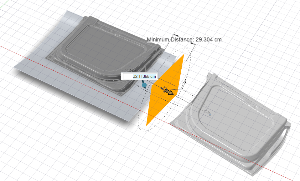
Note: To delete a symmetry plane, select it, and then press Delete. - Optional:
To adjust the symmetry plane, in the guide bar, select one of the following
options:
Option Description 
Global X Axis 
Global Y Axis 
Global Z Axis 
Reference Geometry: In the modeling window, click a reference object. 
Custom : In the modeling window, drag the Phi Angle and Theta Angle arrows, or click one of the arrows and enter an angle. You can also drag the Direction Point. 
Invert Direction