Set Draw Direction
Adjust the draw direction to minimize the depth and avoid negative drafts with the help of the Depth Box and Draft Analysis.
First, you need to define a part. When you assign the part,
the draw direction is calculated automatically and displayed as a blue arrow. To modify
the default draw direction, follow the steps below.
-
Click the Part icon.
-
Click the Draw Direction icon.
-
Turn on visual aids:
- To configure the view, see Configure the View.
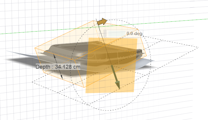
- To display the draw depth, select Depth
Box.

- To display severe negative drafts in red and marginal negative drafts in
yellow, select Draft Analysis.

In the Control Panel, you have the following options:Option Description Draft Angle Define the tolerance value for sufficient draft. The default value is 1.0 degree. Select a value that is greater than or equal to 0 degrees. Severe Negative Draft An angle below the specified Draft Angle is considered a severe negative draft. By default, these regions appear red, but you can change the color using the color palette. Marginal Negative Draft An angle above the specified Draft Angle is considered a marginal negative draft. By default, these regions appear yellow, but you can change the color using the color palette. 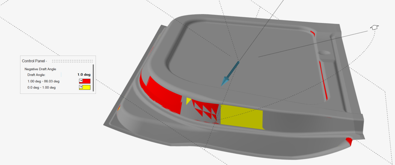
-
Adjust the draw direction to minimize the depth and avoid negative
drafts.
- Drag the Phi Angle arrow.
- In the guide bar, select a reference direction:
Option Description 
Global X Axis 
Global Y Axis 
Global Z Axis 
Reference Geometry: In the modeling window, click a reference object. Note: The reference object must be a planar surface.
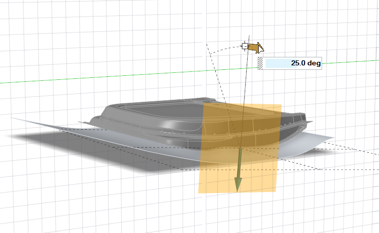
Custom : In the modeling window, drag the Phi Angle and Theta Angle arrows, or click one of the arrows and enter an angle. You can also drag the Direction Point. 
Invert Direction Note: If a symmetry plane has been defined, currently only the Custom and Invert Direction options are available.
- Drag the Phi Angle arrow.