Basic
Create all sorts of glossy materials with sharp highlights like plastic, painted surfaces (including metallic paints), leather, wood, stones, and ceramics. The highlights on plastic materials take on the color of the reflected light, which is usually white.
Main Parameters
- Surface Color
- To define the color, choose from the following options:
- Select a color.
- Select an image. The image overrides the color.
- To blend the color with the image, click the plus symbol (+). You can tell if the blend option is turned on by looking at the image preview.
To define the shade, enter a value of 0-100, where 100 is the true color and 0 is black.
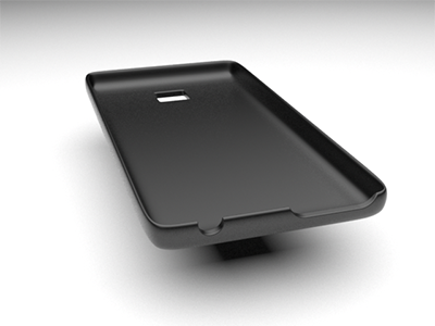
Figure 1. Satin Black Plastic from the Material Library - Reflectivity
- Reflectivity maps are based on black and white values, where white
equals perfectly reflective and black equals perfectly matte.To define the reflectivity map, choose one of the following options:
- Select a color, which will be mapped as grayscale.
- Select an image. Colored images will be mapped as grayscale. The image overrides the color. To blend the color with the image, click the plus symbol (+). You can tell if the blend option is turned on by looking at the image preview.
- To define the strength of the reflections, enter a value of 0-100, where 100 produces perfect mirror reflections and 0 produces the weakest reflections.
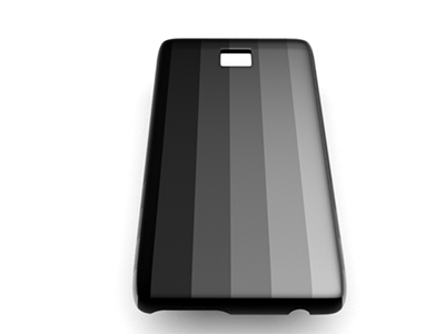
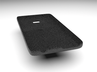
Figure 2. Satin Black Plastic with the Image Gray_Scale.jpg (Contrast 50), White (Default Color), and Reflectance 50%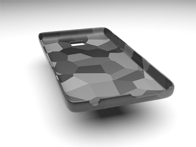
Figure 3. Satin Black Plastic Blended with the Image Noise09.jpg (Molds Folder) - Index of Refraction (N)
- Define the reflectivity of the surface. Higher values correspond to more
intense reflections.
If you selected a preset, this value is predefined. If you selected a custom preset, look up the index of refraction online.
- Reflectivity Boost
- Enhance the reflectivity.
- Translucent
- Make the material semitransparent.
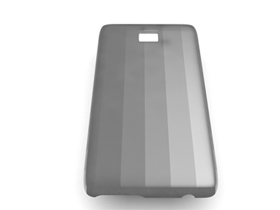
Figure 4. Same Settings as Those Used for the Reflectivity Example But with 75% TransparencyTranslucency: To apply a translucency map, select a color and/or an image. To define how deep light is absorbed, enter a value of 0-100. At 0, no light is absorbed (all light is reflected); at the default value of 100, all of the light is absorbed (no light is reflected). Play with the higher values to make noticeable changes; the slightest adjustment can make a difference.
Absorption Color: A translucent object is colored by the light it absorbs. Define the color of the light by selecting a color from the color palette.
Absorption (1/m): Define the thickness (in meters) at which the object takes on the internal color. The default value is 0.
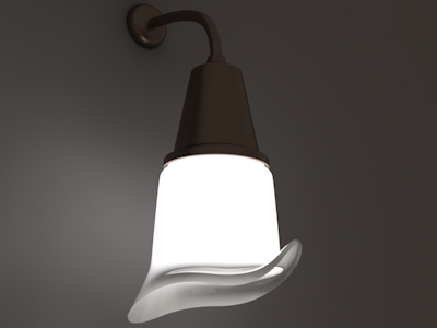
Figure 5. Opal Glass Simulated Using the Default values of 100 for Translucency and 0 for Absorption - Roughness
- Roughness adds texture to the material at a microscopic level. When you
modify the roughness, the surface texture still looks the same; however,
tiny changes invisible to the naked eye have occurred, affecting
reflectivity.
0 can produce a perfect mirror reflection.
Lower values produce crisper and brighter reflections.
Higher values produce blurrier, dimmer reflections. Increasing the roughness spreads and distributes reflections over the surface and creates a more matte surface.
At values approaching 100, light becomes so scattered that reflections are barely visible, if at all.
- Bump
- Bump adds texture to the material at a macroscopic level. Because it
visibly affects the surface texture, Bump is useful for simulating
irregular surfaces.A bump map gives the illusion of texture without physically distorting the geometry, minimizing rendering time. The grayscale map tells Inspire Render how to change the surface normals as if the surface had been displaced; the modified normals are used in lighting calculations. A bump map looks like the inverse of what you might expect: black represents the highest extreme and white represents the flattest extreme, while shades of gray represent grades in between.
No Bump (default): Do not use a bump map.
Use Surface Color for Bump: Reuse the image used for your color map and apply it as the bump map. You can make the bumps look taller or flatter by adjusting the bump effect (0 to 100); higher values make the texture look more pronounced, smaller values make the texture look more subtle.
Custom Bump: Upload an image. You can make the bumps look taller or flatter by adjusting the bump effect (0 to 100); higher values make the texture look more pronounced, smaller values make the texture look more subtle.
Normal Map OpenGL: Achieve more detailed texture effects when you have uploaded a RGB color image. While standard bump mapping uses grayscale values to describe the surface's hills and valleys in terms of height, normal mapping translates red, green, and blue values to x, y, and z coordinates, creating texture in terms of angles up the hill or down the valley.
Normal Map DirectX: Achieve more detailed texture effects when you have uploaded a RGB color image. While standard bump mapping uses grayscale values to describe the surface's hills and valleys in terms of height, normal mapping translates red, green, and blue values to x, y, and z coordinates, creating texture in terms of angles up the hill or down the valley.
Advanced Parameters
- Anisotropy
- Stretch and blur highlights. Anisotropic reflections are like regular reflections, except they are stretched and blurred against the grain of the material. They are often used to simulate finely brushed metals.
- Rotation
- Enter a value from 0 to 360 to rotate the stretched highlights. Rotation is only applicable if Anisotropy has been selected.
- Micro Roughness
- Adjust the sharpness of reflections, as the viewing distance goes from
close to far. When you look at a surface that is uniformly rough, areas
that are closer appear rougher (because you can see them more clearly)
while areas that are farther away appear smoother (because you can't
seem them as clearly). As a result, nearby reflections look blurrier
while faraway reflections look crisper.
Height (μm): Adjust the average height of the bumps on the surface. Higher values correspond to blurrier reflections overall.
Width (μm): Adjust the average width of the bumps on the surface. Higher values correspond to blurrier reflections overall.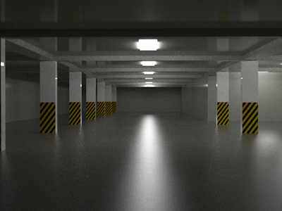 Figure 6. Micro Roughness Disabled
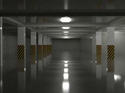 Figure 7. Micro Roughness Enabled with a Width of 10
μm and Height of 0.1 μm
Figure 7. Micro Roughness Enabled with a Width of 10
μm and Height of 0.1 μm - Medium
- The medium is the area between the upper and lower surfaces of a thick,
transparent material. It affects how light travels through the material.
This is useful for rendering liquids (e.g., water, wine, beer, oil) or
atmospheric effects (e.g., fog, dust particles,
caustics).
Absorption Color: Define which colors of the spectrum are absorbed (thus not visible) by uploading an image or picking a plain color. The remaining colors of the spectrum are reflected (thus visible).
Absorption Density: Use to adjust the intensity of the Absorption Color.
Scatter Color: Define which colors are scattered by uploading an image or picking a plain color. The material is tinged with these colors.
Scatter Density: Adjust the intensity of the Scatter Color.
- Displacement
- Bump allows you to render detailed textures relatively quickly; however,
because you are only changing the surface normals and not the surface
itself, silhouettes and shadows might not be rendered realistically.
This condition is particularly true for larger texture effects. If you
need to give surfaces a greater sense of depth and detail, showing
self-occlusion, self-shadowing, and silhouettes, use Displacement. Like
bump maps, displacement maps are grayscale; black equals zero
displacement and white equals maximum displacement (a value you define
using the Height parameter below).
This feature is not currently available in GPU+CPU mode.
The default number of samples is 500.
Subdivision: Modify the object's number of subdivisions before displacement occurs. Higher values produce more accurate results.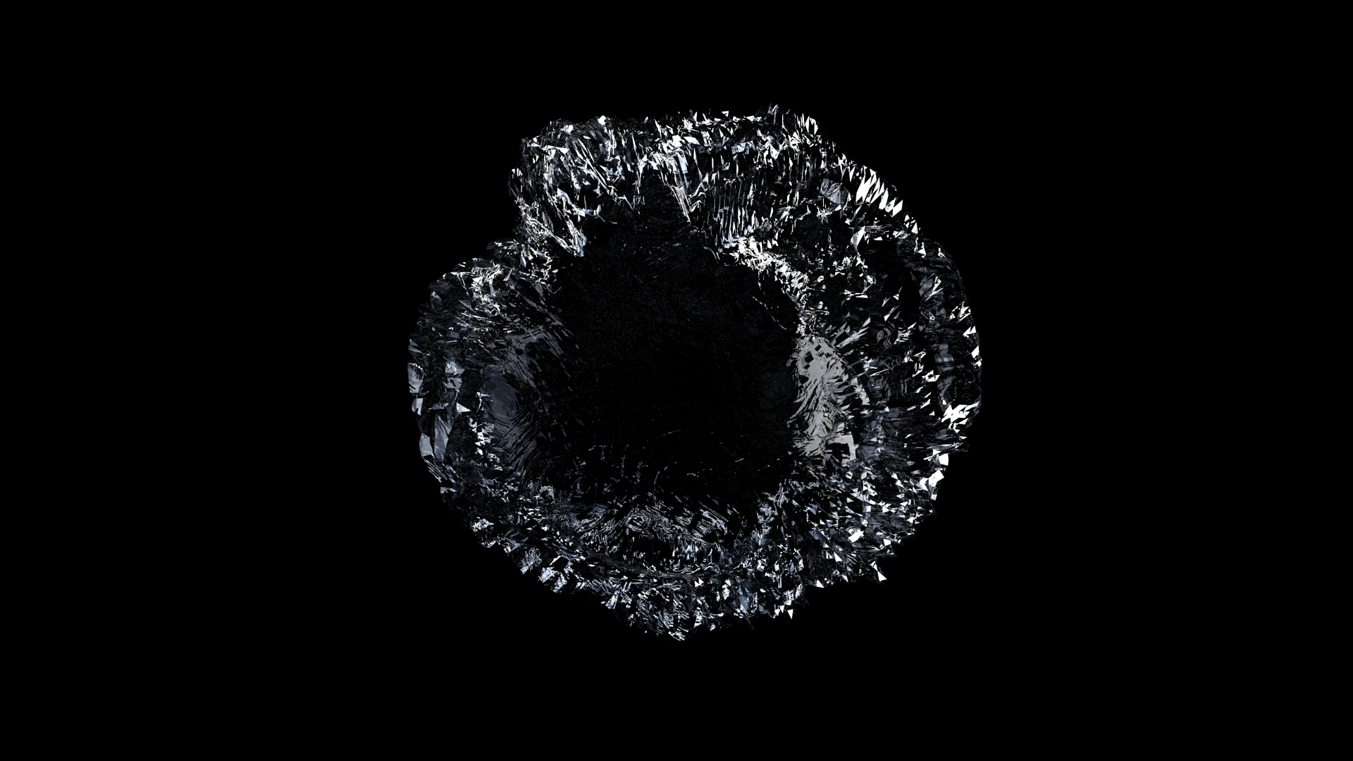 Figure 8. Subdivision: 2
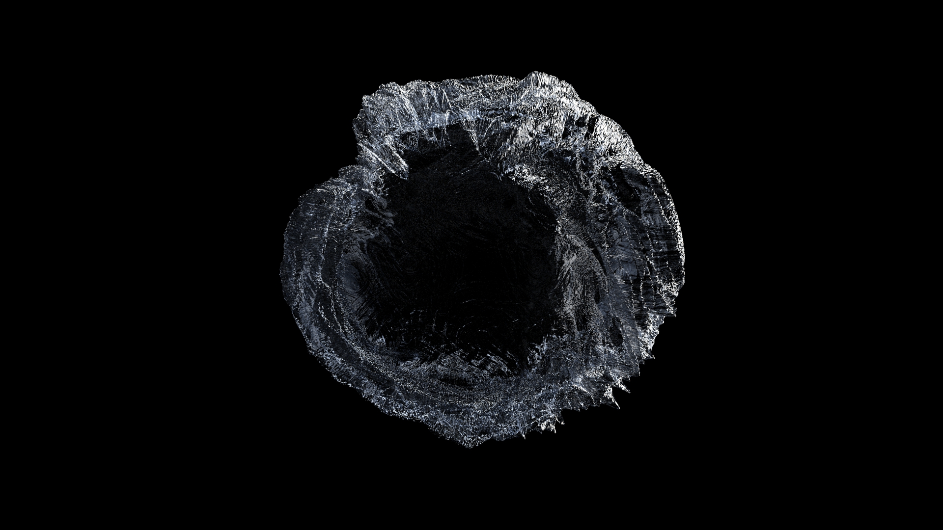 Figure 9. Subdivisions: 6
Texture: Upload a texture map. Colored images will be mapped as grayscale.
Height: Set the maximum distance displaced. For displacement to appear, values must be greater than zero; the default is 2 cm.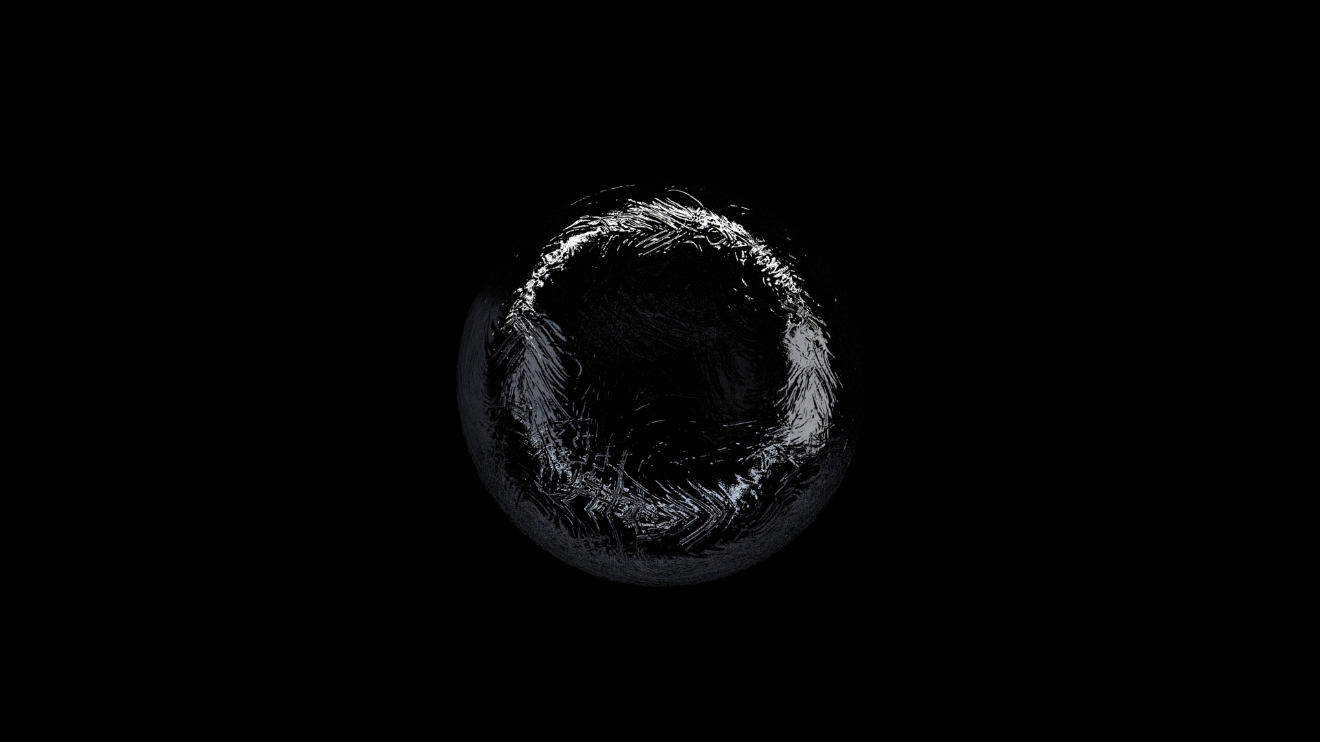 Figure 10. Height: 0.5cm
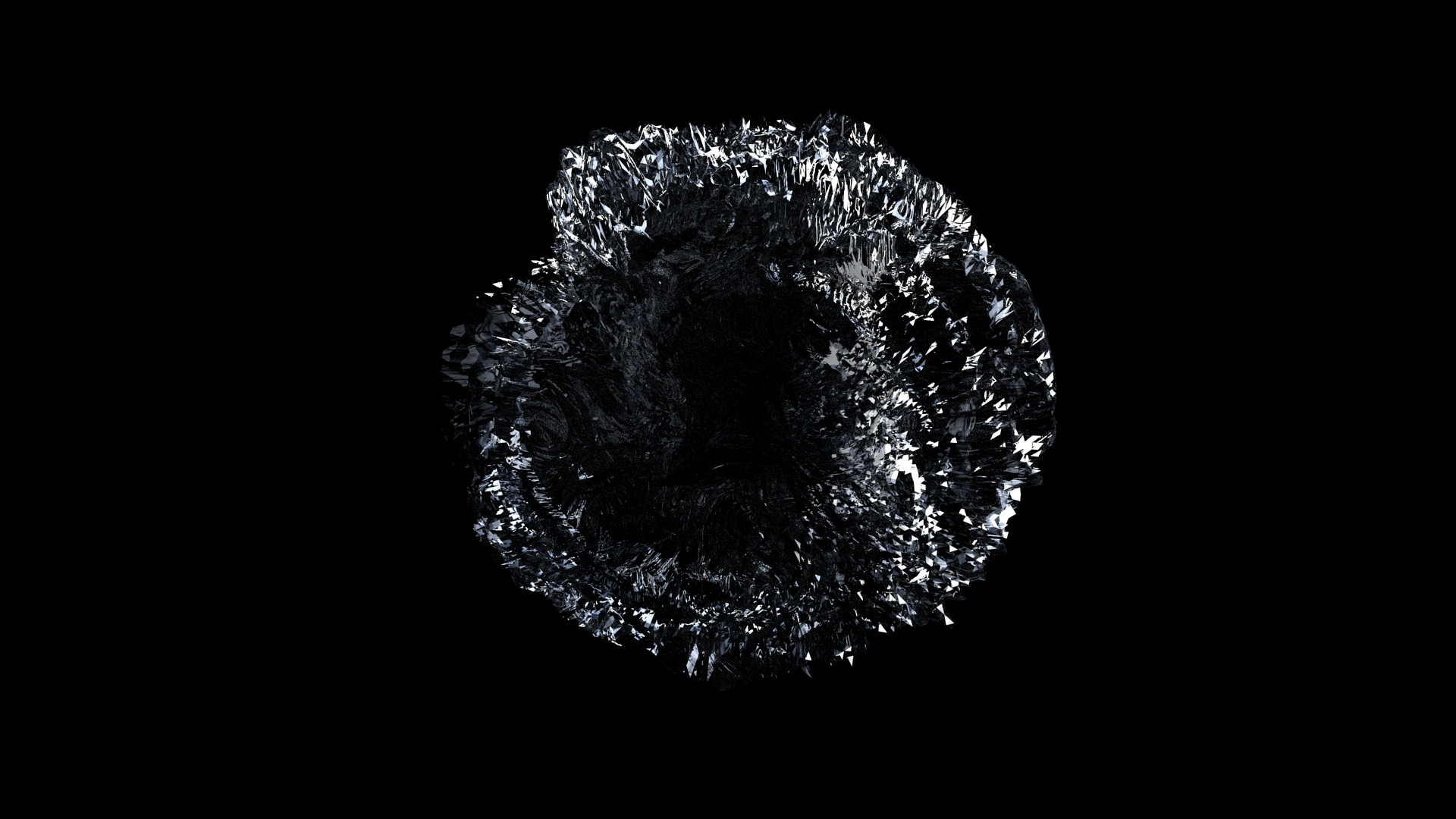 Figure 11. Height: 25cmCenter: Invert displacement. This feature is useful for positioning objects along a ground plane. For example, adding a displacement map to a carpet may make it look like it's floating. Reducing your center will bring it back down to the floor. Adding a displacement map to a floor may result in objects intersecting with the floor. In this case, you could increase the center to avoid intersection.
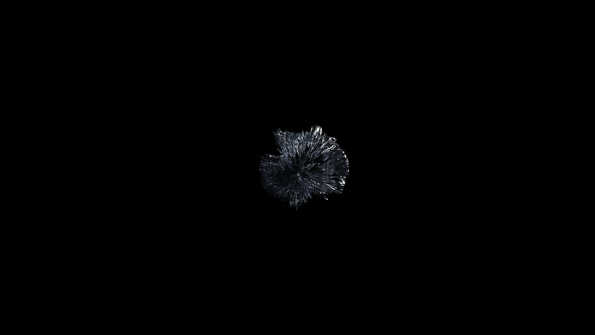 Figure 12. Center: 1cm
 Figure 13. Center: 0.1cmNormal Smoothing: Enabled by default, to render smoothly (continuous shading). Disable to render in a faceted way, which is useful for rendering very sharp, detailed displacements such as sharp corners.
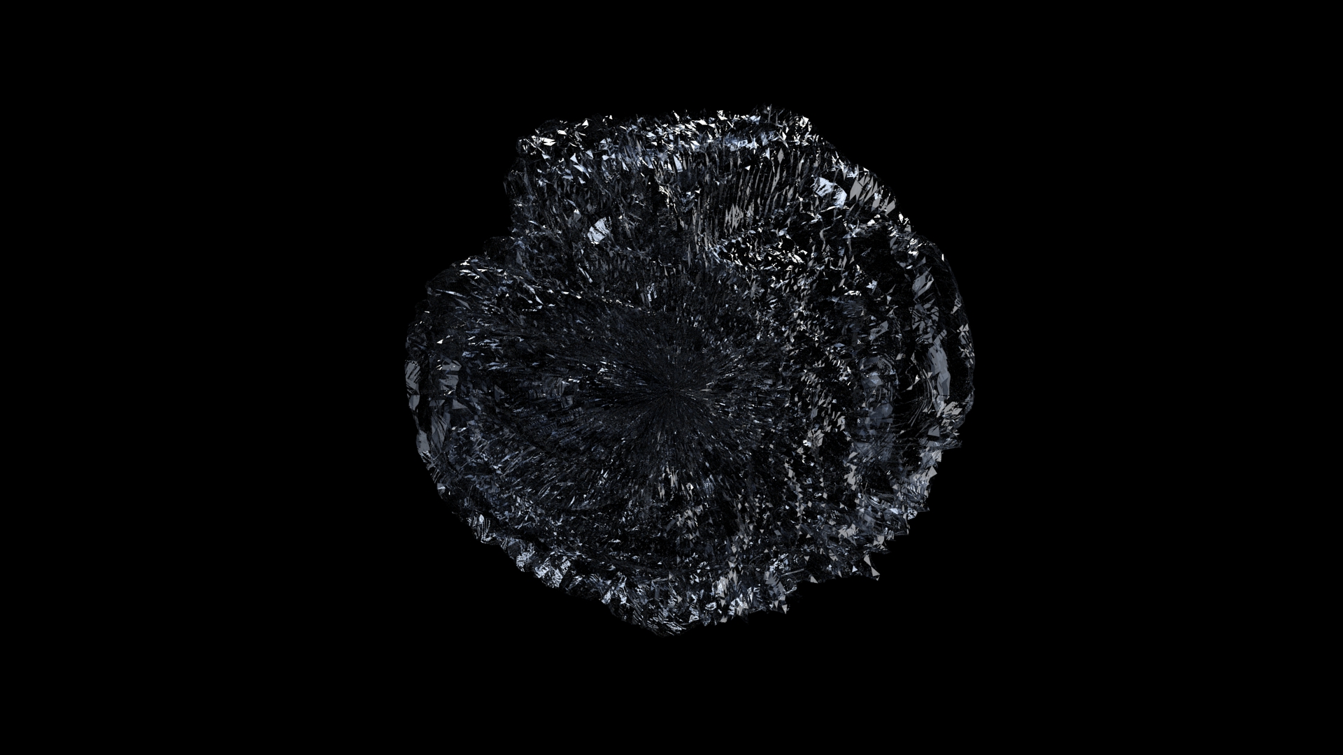 Figure 14. Normal Smoothing Disabled
 Figure 15. Normal Smoothing OnTight Bounds: Enabled by default. This feature lets Inspire Render compute more precise bounding volumes for the displaced surface, leading to slightly better rendering times. Since this feature is performance-based, check your engine settings to enable your fastest processors.
 Figure 16. Tight Bounds Disabled
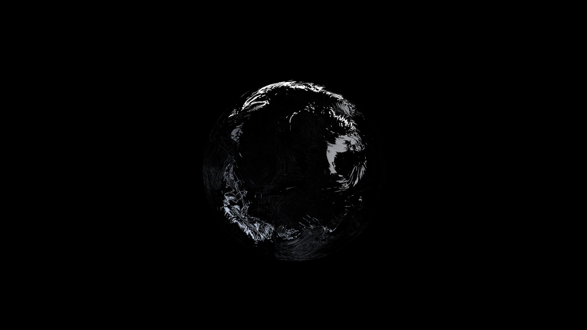 Figure 17. Tight Bounds Enabled
 - Clipping
- Make areas of the material transparent, using a grayscale texture map
where black equals completely transparent and white equals completely
opaque. This is useful for quickly creating perforated materials like a
mesh, since you can skip modeling the holes by
hand.
Texture: Upload a texture map. Colored images will be mapped as grayscale.
Threshold (%): Change how the texture map is interpreted. The default is 50, where 50% gray is interpreted as 50% transparent. To make a greater area of the texture transparent; increase the threshold; to make a greater area of the texture opaque, decrease the threshold. At 100, all of the texture is transparent; at 0, all of the texture is opaque.