Runner
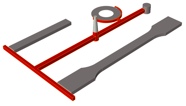
The runner is the material distributor, taking the material from the sprue to the gates.
Location: Molding tab, Runner System icon
Automatically Create Runner System
If your model geometry does not include a runner system, you can create a virtual runner system automatically with the Runner tool.
Location: Molding tab, Runner System icon secondary ribbon, Runner icon
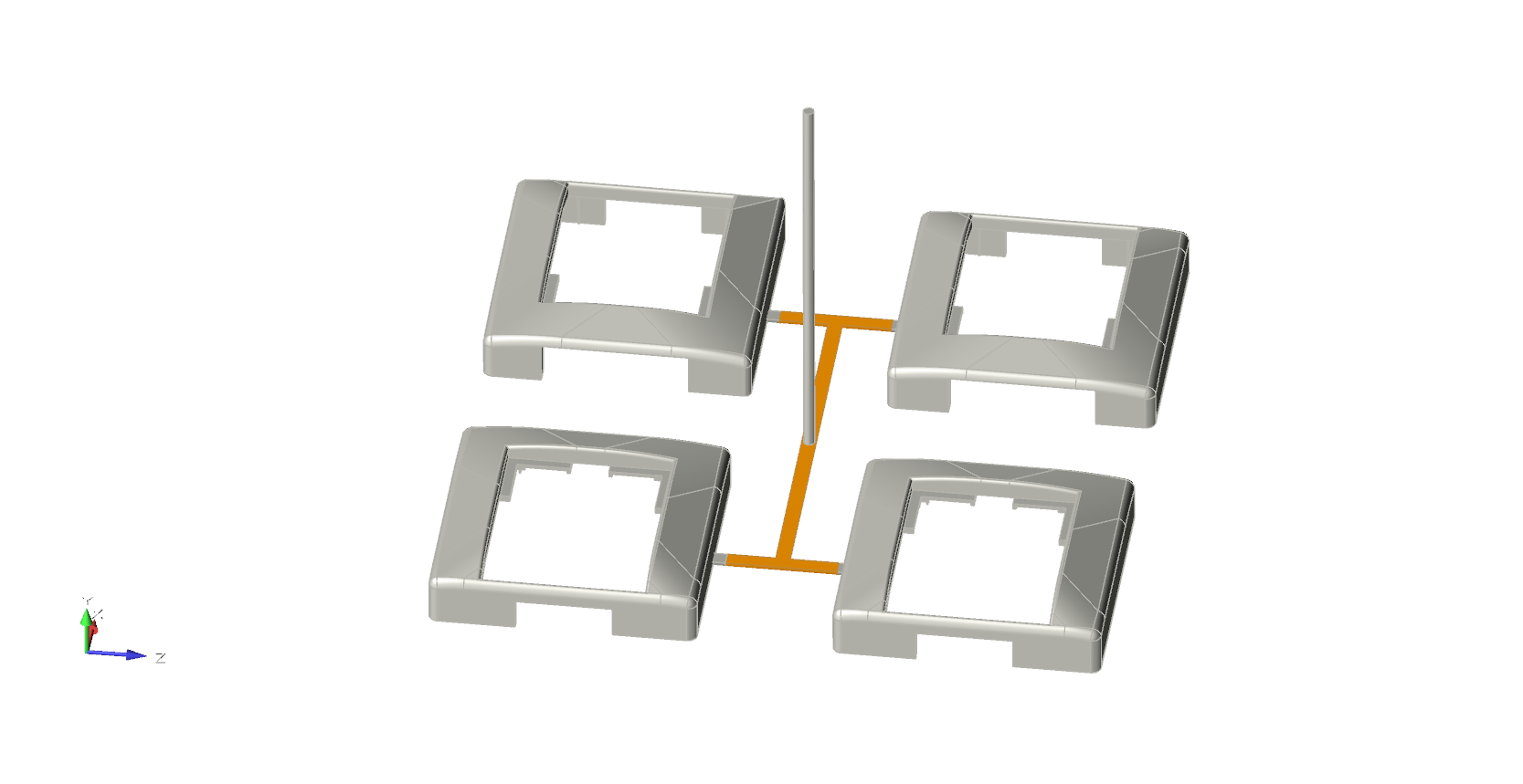
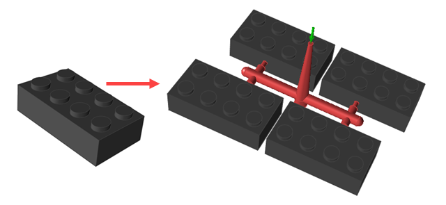
After you define the required number of part cavities for your model, the Runner tool generates the entire runner system for the model including the gate, runner, sprue and injection point.
-
Click the Runner System icon.

-
Click the Add/Edit Runner icon on the secondary ribbon.

-
Enter the parameters for your part(s) and runner system on the Create Runner
dialog.
Parameter Description No Cavities Enter the number of part cavities to fill. Keep the default of 1 or enter increments: 2, 4, 8, 16 or 32. Cross Section Select Circular or Square for the shape of the runner. 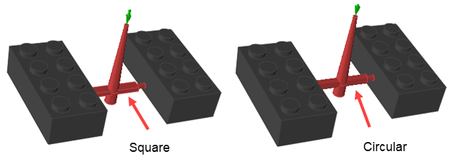
Initial Runner Radius or
Initial Runner Width and Height
Define the cross section for the runner segment that initially attaches to the sprue. If you selected a circular cross section, enter its radius. If you selected a square cross section, enter its width and height. 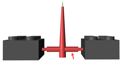
Sprue Height Enter the height of the sprue. 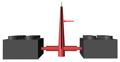
Sprue Puller Depth Enter the sprue puller depth. 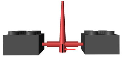
Runner Depth Enter the runner depth. 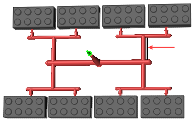
Runner Final Section Depth Enter the depth of the runner section that attaches to the gate. 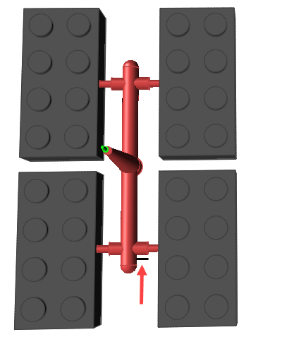
Parts Separation Enter the distance between parts. 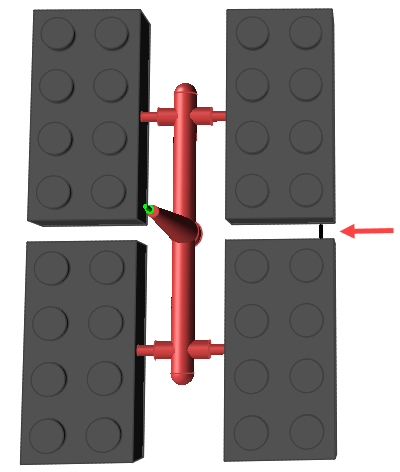
-
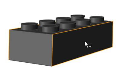
Select a surface of the part where you want to attach the gate of the runner
system.
Note: If your part already includes a designated gate, you do not need to select a surface. The runner will automatically attach to the existing gate.
The software automatically generates the runner system for your model.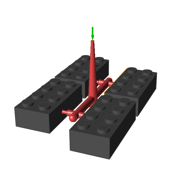
Designate Runner
Identify any runners that are included in your model geometry.
-
Click the Runner System icon.
-
Click Designate Runner on the
Runner icon.

-
Click the predesigned runners.
Selected runners are displayed in dark red.
Define Hot Runner
Identify existing runners as hot runners and define the hot runner system.
Create or designate a runner system before defining it as a hot runner system.
-
Click the Hot Runner icon.

-
Use the options in the microdialog to define the Hot Runner system for your
model:
- Select the Hot Runner check box to indicate that you want to define the runner system in your model as a hot runner.
- Choose a type of hot runner system and define the associated parameters:
Hot Runner System Description Insulated The runner parts are insulated to maintain the material temperature. Heat controls are not applied in this type of runner. Temperature A constant heat source is applied to the runner system to maintain the temperature of the material. Set the temperature of the heat source. - Double right-click to confirm the hot runners.