Part Cavity
Designate the part cavities in your model geometry, automatically define part cavities and a runner system, and reorient part cavites.
Location: Molding ribbon

Automatically Detect Cavities
Click the inlet surface to automatically select and define the mold part cavities and running system.
-
On the Part Cavity icon, click Auto Configure
Components.

-
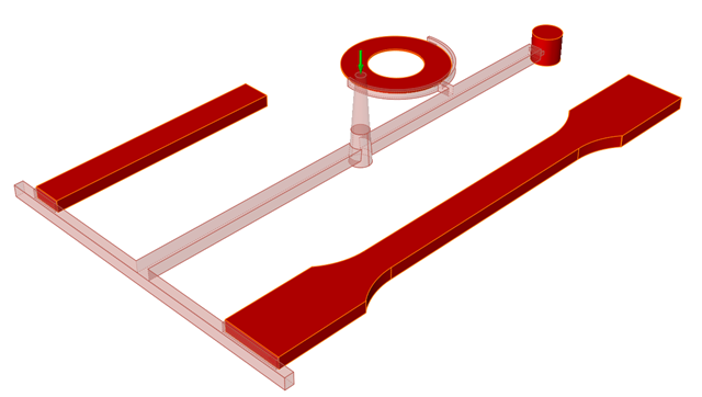
Click the surface of the inlet to automatically detect the mold part cavities
and the runner system components.
The mold part cavities are displayed in dark red and the runner system components in light red. The selected inlet has a green arrow.
-
Use the microdialog options to define the material type, polymer and
temperature.
Option Description Note 
Click the Materials Viewer to examine the material's thermal, rhealogical, mechanical, PVT and fiber properties. You can use the Material Viewer to modify an existing material, save it with a new name, and access it from the My Materials tab. 
Select a material type. 
Select from common polymers of your chosen material type. 
Enter the temperature of the material.
Designate a Cavity
Select the molding parts and define the material, polymer, and temperature.
Note: You need to designate a part cavity before performing any other
operation.
-
On the Part Cavity icon, click Designate Part
Cavity.

-
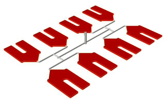
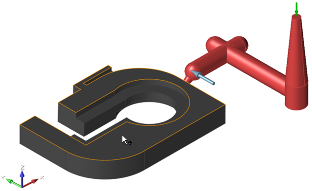
Select the part cavity in your model. If your model contains more than one part
cavity, select them all.
The selected parts are displayed in red.
-
Use the microdialog options to define the material, polymer, and
temperature.
Option Description Note Click the Materials Viewer to examine the material's thermal, rhealogical, mechanical, PVT and fiber properties. You can use the Material Viewer to modify an existing material, save it with a new name, and access it from the My Materials tab. Select a material type. Select from common polymers of your chosen material type. Enter the temperature of the material.
Reorient a Cavity
Reorient a part cavity to a mold opening.
Note: You need to designate a part cavity before performing any other
operation.
The Reorient Cavity tool lets you change the orientation of your part cavity in respect to the mold opening direction.
-
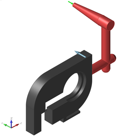
On the Part Cavity icon, click Reorient
Cavity.

A gray arrow appears indicating the direction of the mold opening. The following example shows the mold opening direction on the Y-axis: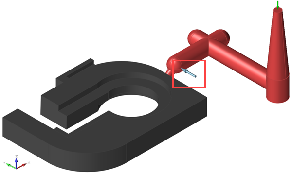
-
Determine the optimal orientation of the part cavity to the mold opening
direction. Based on that orientation, select the face of the part cavity that it
is perpendicular to the mold opening direction.
In the following example, the part cavity face with the most surface area is selected to be reoriented to the mold opening. The selection is outlined in yellow.
After you select a face, the model reorients with the face perpendicular to the mold opening.