Tutorial: Surface Modeling
Analyze a surface model, create surfaces using the Midsurface and Patch tools, then optimize the surfaces.
- Import surfaces from CAD
- Assign a thickness to a surface using the Property Editor
- Midsurface simple and complex thin solids
- Create surfaces from solids using the Patch tool
- Analyze and optimize surfaces
Overview
Surface or "shell" models are a way of representing thin-walled 3D structures in a numerically accurate and efficient way. They are often used when the thickness of a part is significantly thinner (approximately 1/10th or less) than its other standard dimensions. Using surface models in these cases can produce much shorter analysis and optimization run times.
- Importing surfaces from CAD.
- Using the sketching tools in Inspire.
- Applying the Midsurface tool to a thin solid generated from CAD or in Inspire.
- Applying the Patch tool to a thin solid generated from CAD or in Inspire.
Analyze a Surface Model
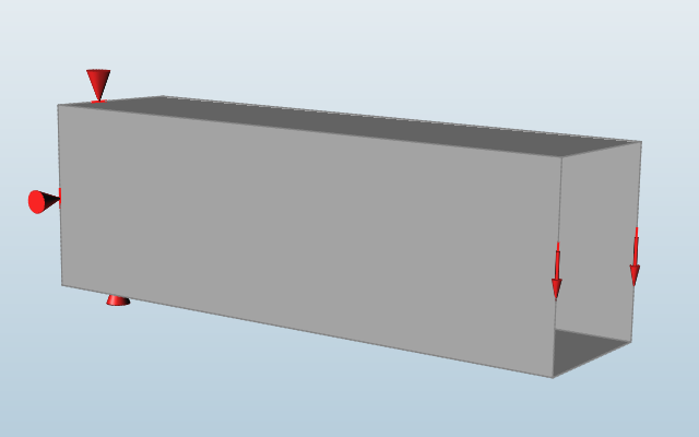
Let's start by exploring the benefits of using surfaces.
-
Double-click the rhs_01.stmod file to load it in the
modeling window.
-
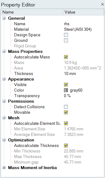
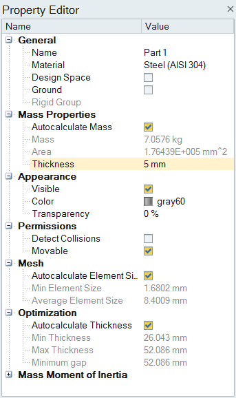
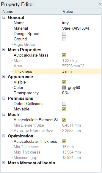
Press F3 to open the Property Editor. A thickness of 10
mm has been assigned to the part under the Mass Properties.
-
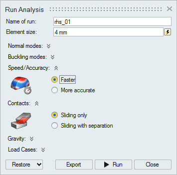
Click the
 button on the Analyze icon to set up an analysis
using the following options.
button on the Analyze icon to set up an analysis
using the following options.
-
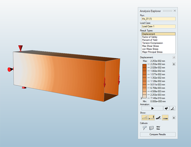
Double-click the run name to open the Analysis Explorer
and examine the Displacement and other results.
Import CAD and Assign a Thickness
One way to obtain a surface is to import a CAD model into Inspire.
Note that all surfaces must be assigned a thickness in the Property Editor. Failure to assign a thickness will prevent contacts from being detected and result in failed runs.
-
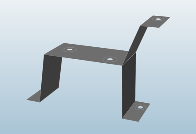
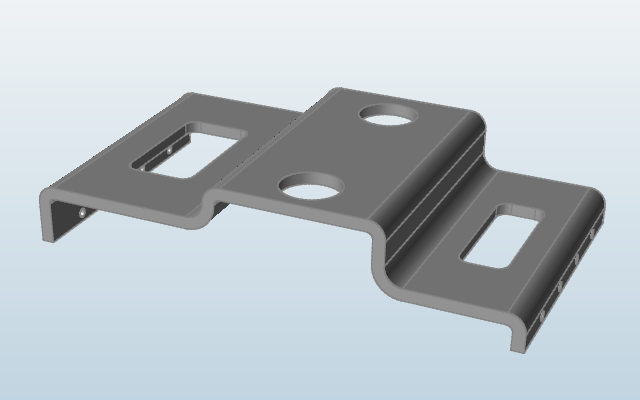
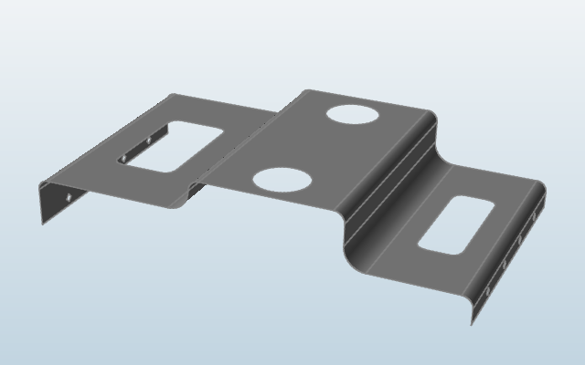
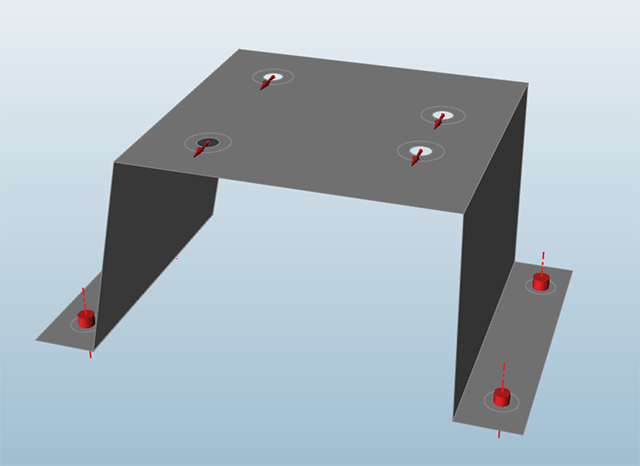
Double-click the sheet_metal_bracket.x_t file in the Demo
Browser to import the CAD model into Inspire.
-
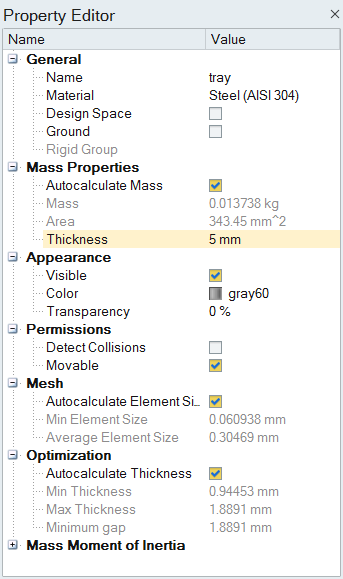
Select the Tray part and enter a Thickness of
5 mm under Mass Properties in the Property
Editor.
-
Select the Contacts tool on the Structure ribbon to
search for contacts, and orbit the model.

-
One contact is found and indicated by the thick blue lines on the shared part
boundaries.
Inspire uses a part-to-part contact definition with the boss regions and the main structure in separate parts, so this is the expected behavior.
Create Surfaces Using the Midsurface Tool
Surfaces can also be created directly in Inspire by applying the Midsurface tool, which automatically detects thin solids and allows you to replace them with a surface.
- This restricts the target parts to those that can be formed or bent from a flat initial sheet.
- Slots, holes, and cut-outs are allowable.
- Constant section non-manifold parts such as extrusions are supported.
- Partitioning of parts prior to midsurfacing and subsequent connection with other parts can often be performed.
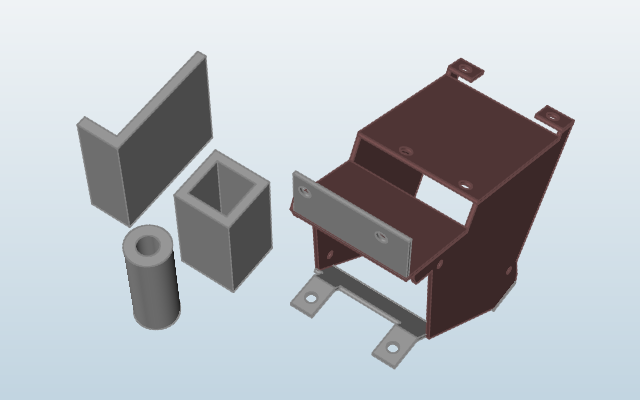
-
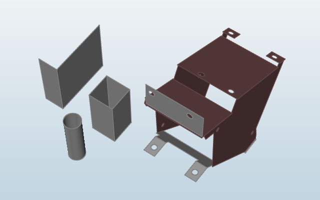
Double_click the midsurface_examples.stmod file in the
Demo Browser.
This model contains a number of thin solids that meet the requirements for midsurfacing.
-
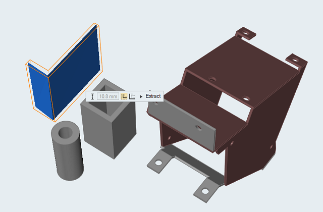
Select the Midsurface tool on the Geometry ribbon.

-
Select the L part in the modeling window to replace it
with a midsurface.
A preview of the midsurface is shown. The thickness is automatically calculated and displayed in the microdialog, but cannot be edited.
-
Double-right-click to exit the tool, then select the newly created
midsurface.
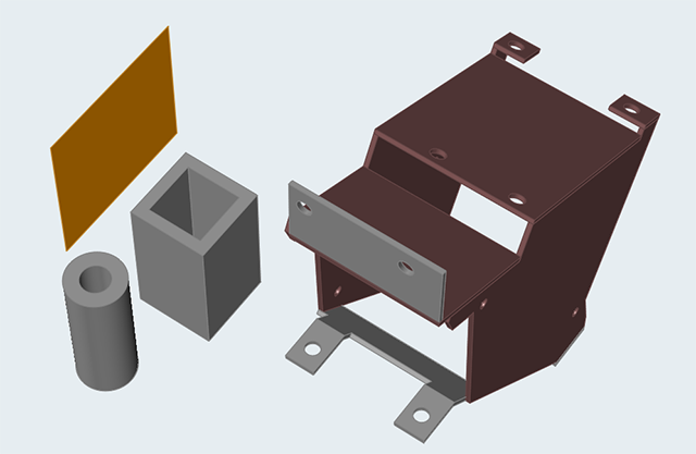
-
Check the Property Editor and note that a thickness has been assigned to the
midsurface.
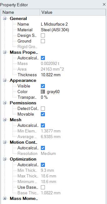
Note: The Midsurface tool automatically calculates thickness and assigns it to the part. Surfaces created using another method must have a thickness assigned manually in the Property Editor. -
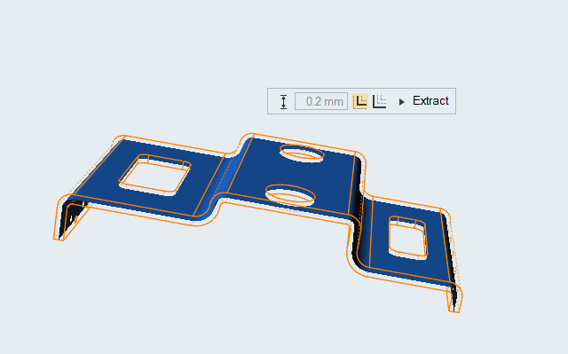
Click Extract on the guide bar to extract the
midsurfaces.
Note: Note that while the parts in the fabricated bracket assembly are correctly midsurfaced, they are not necessarily aligned.
-
Now open the plate.x_t file located in the Demo
Browser.
This is a more complex model.
-
Select the part in the modeling window. A preview of the midsurface is
shown.
Note: Even though the part has holes and curvature, it is a constant section and satisfies the criteria for a valid thin solid.
-
Click Extract to create the midsurface and
double-right-click to exit the tool.
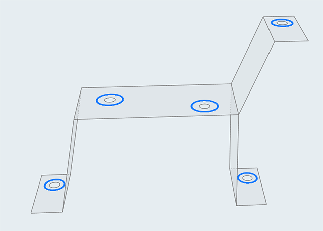
Create Surfaces Using the Patch Tool
Another way to create a surface is by applying the Patch tool to a solid.
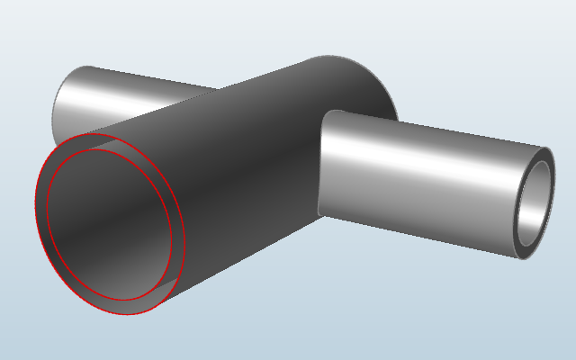
More often used to close and repair geometry, the Patch tool can also be used to delete surface patches on the solid. This is very powerful because as soon as any solid has a patch deleted it becomes a surface. For example, the RHS model at the beginning of the tutorial was created by deleting the ends of a solid rectangular box.
-
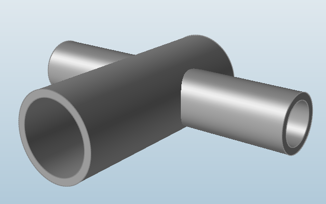
Open the x-tubes.stmod file in the Demo Browser.
This model is a simple 3D structure created in Inspire, but could also have been imported from CAD.
-
Select the Boolean tool on the Geometry ribbon.

-
Select the Combine tool from the secondary ribbon.

A guide bar appears, with Targets selected. -
Right-click and mouse through the check mark to exit, or double-right-click.
The tubes are now a single part.
-
Select the Patch tool on the Geometry ribbon.

-
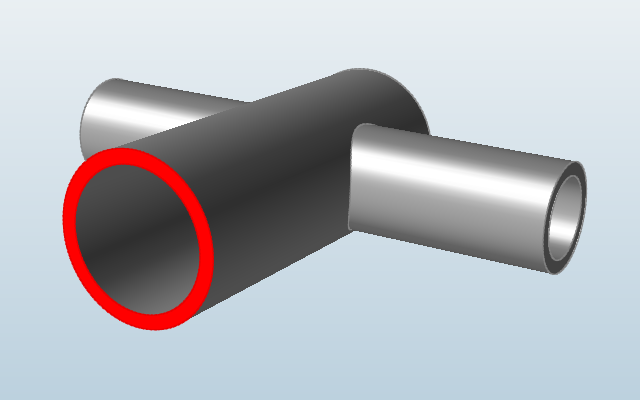
Click the face on the end of one of the tubes to select it.
You may need to zoom in to select the face.
-
Click again to delete the face.
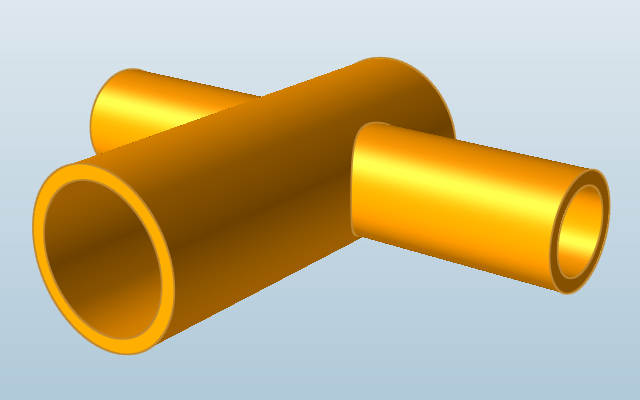
As soon as it is deleted, the solid part becomes a surface, and an area rather than a volume is shown in the Property Editor.
-
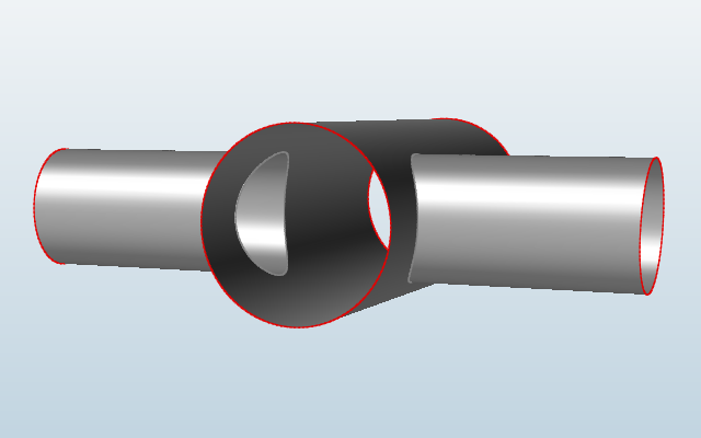
Use the same process to remove the remaining three faces from the ends of the
tubes, as well as all of the interior surfaces.
The model should look as shown below:
-
Select the part and enter a Thickness of 5
mm in the Property Editor.
Note: The Mass is automatically calculated.
Optimize a 2D Surface Model
-
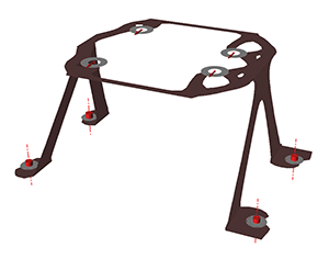
Open the 2dtopology_and_contact.stmod file from the Demo
Browser.
This model contains both geometry and loads.
-
Select the Tray part and enter a
Thickness of 3 mm under Mass
Properties in the Property Editor.
-
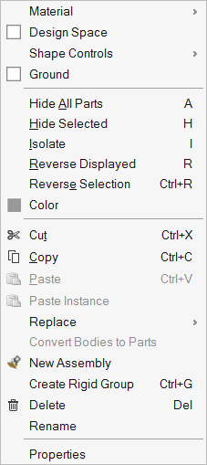
Right-click on the Tray part to open the part context
menu and designate it as a Design Space.
-
Select the Add/Edit Symmetric Controls tool on the
Structure ribbon.

-
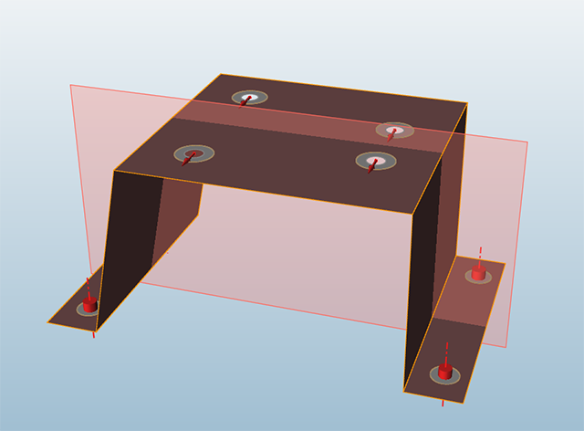
Select the Symmetric tool from the secondary
ribbon.

-
Select the Tray part to apply a symmetry plane as
shown:
-
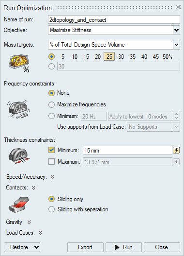
Click the button on the Optimize icon to set up an
optimization with a Mass Target of
25% and a Minimum Thickness
Constraint of 15 mm: