Learn how to break a part into multiple parts, copy reference geometry, trace curves,
and use Boolean intersection to create a new part.
In this lesson you will learn how to:
Import a CAD model
Break a part into multiple parts
Copy reference geometry
Trace curves using sketch tools
Pull a sketch curve into a solid
Use Boolean intersection to create a new part
Define a design space
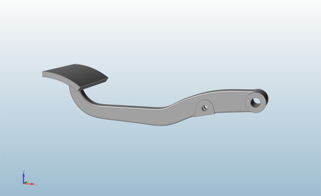
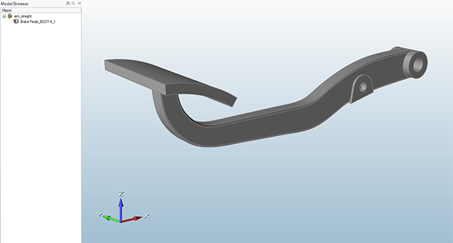
Import the CAD Model
Press F7 to open the Demo Browser.
Double-click the arm_straight.x_t file to load it in the
modeling window.
Make sure the display units in the Unit System Selector are set to
MMKS (mm kg N s).
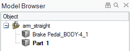
If not already visible, press F2 to open the Model
Browser.
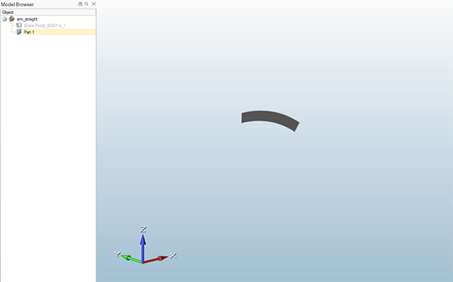
Copy Reference Geometry
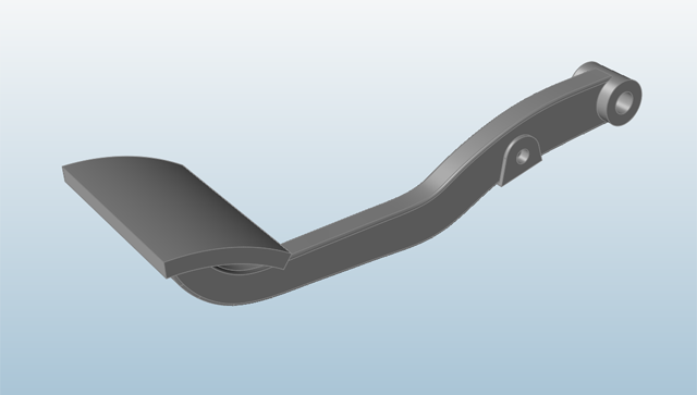
Use the middle mouse button to adjust the view so the model is positioned as
shown below.
Click the icon in the lower left corner of the modeling
window to Switch to Orthographic Projection.
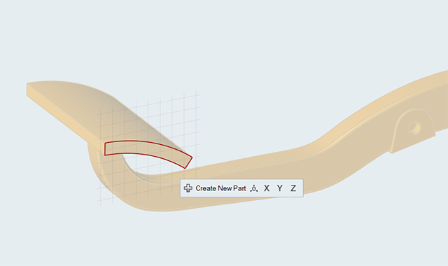
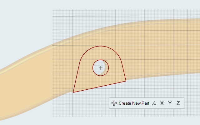
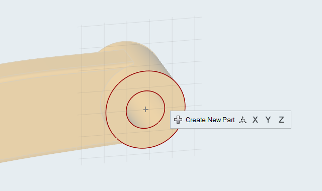
Double-click the side face of the break pedal twice to enter sketch mode.
A sketch plane is created perpendicular to the selected face, and the
edges of the face are outlined in red.
Note: The red reference lines are created only on the side face of the
brake pedal, because this is the only face that touches the sketch
plane.
Click the Create New Part button on the microdialog to
place what you are about to sketch into a new part, which appears in the Model
Browser.
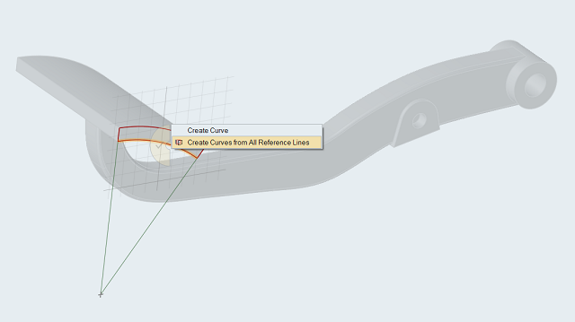
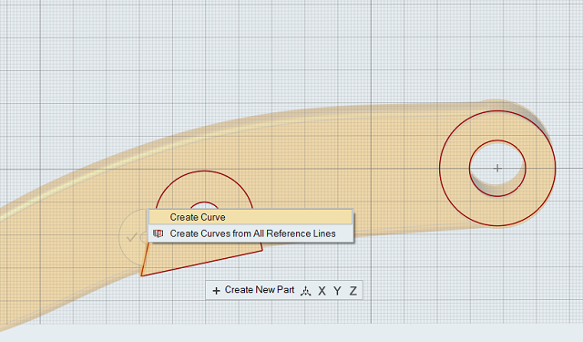
Click the Convert Lines icon on the sketch toolbar, or right-click one of
the red reference lines and select Create Curves from All Reference
Lines from the context menu.
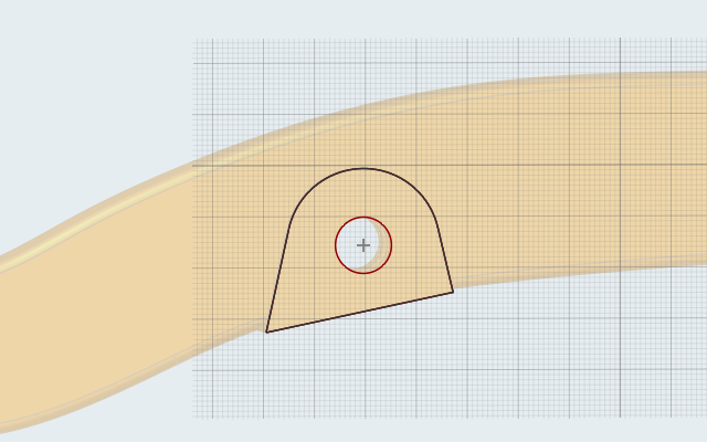
The reference lines are copied and now appear black.
Double-right-click to exit sketch mode and enter push/pull mode.
Pull the Sketch Curve into a Solid
Click the cube icon next to the original part in the Model Browser to hide it
in the modeling view.
Only the new part you just sketched is now visible.
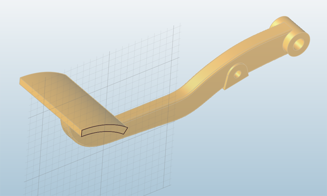
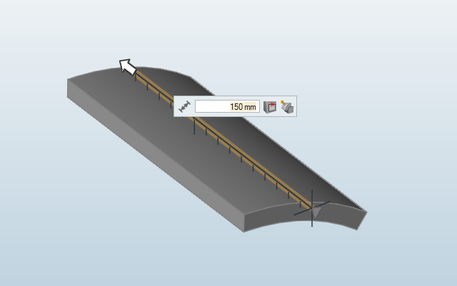
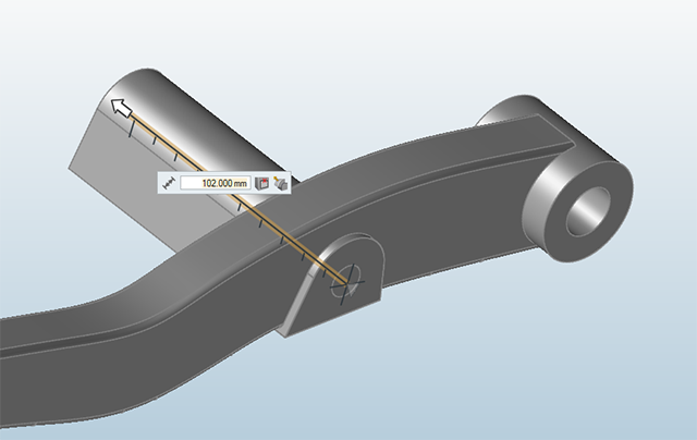
While in push/pull mode, click and drag on the face to extrude it into a pedal.
Be sure to extend the face away from you beyond the far edge of the pedal in the
original model.
Double-right-click to exit push/pull mode.
Click the cube icon next to the original part in the Model Browser to make it
visible in the modeling view again, and left-click to deselect all
objects.
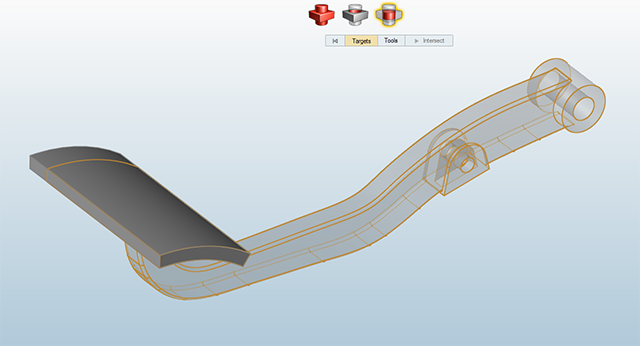
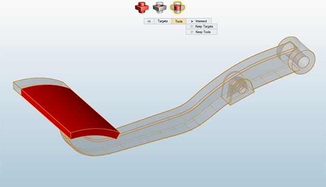
Use Intersection to Create the Pedal
Select the Boolean tool on the Geometry ribbon.
Select the Intersect tool from the secondary
ribbon.
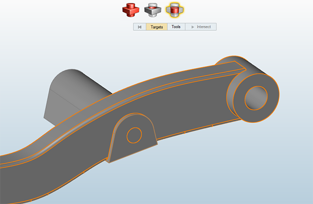
Click on the brake arm in the modeling window to select it.
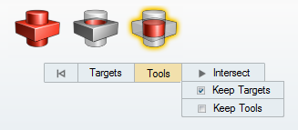
Click Tools on the guide bar.
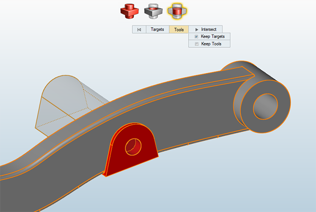
Click on the pedal (the part you extruded in the previous step) to select
it.
Select the Keep Targets check box on the guide
bar.
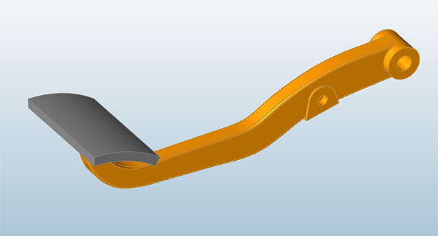
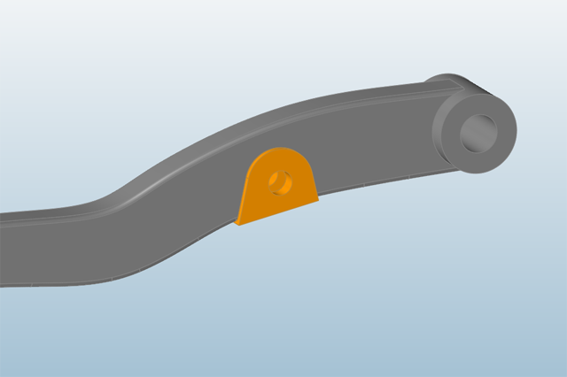
Click the Intersect button on the guide bar to perform
the operation. Double-right-click to exit the tool and then select the brake
arm.
The pedal and the arm are now two separate parts.
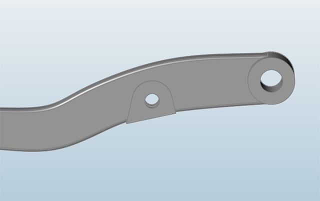
Copy Individual Curves
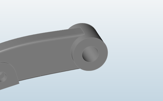
Another way to duplicate geometry is to copy individual curves. Adjust the view
and use the scroll wheel to zoom in on the primary cylinder, as shown
below:
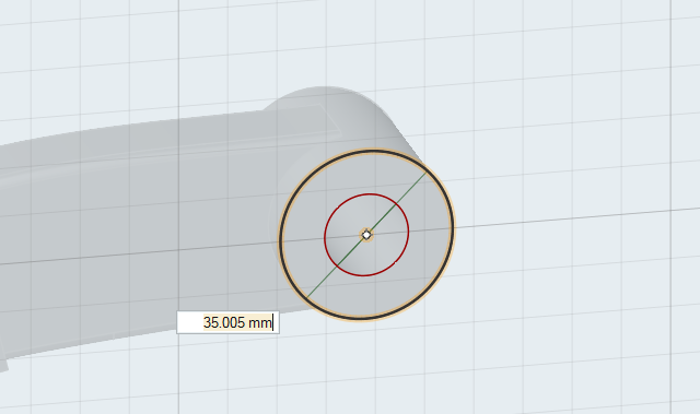
Double-click the face of the primary cylinder once to enter push/pull mode, then
double-click again to enter sketch mode.
A sketch plane is created perpendicular to the selected face, and the
edges of the face are outlined in red.
Right-click one of the edges of the face and select Create
Curve from the context menu. Repeat this step for all four outer
edges of the face, but not the interior circle.
Once selected, the outer edges of the primary cylinder should appear
black.
Click the Transfer Sketch icon on the sketch toolbar to
transfer the sketch you just created to a new part.
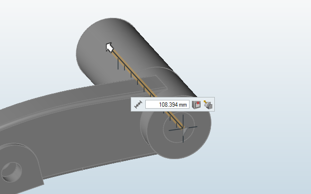
Double-right-click to exit sketch mode and enter push/pull mode.
Click and drag to extrude the sketch into a solid. Be sure to click inside the
circle so that you select the whole face.
Right-click and mouse through the check mark to exit, or double-right-click.
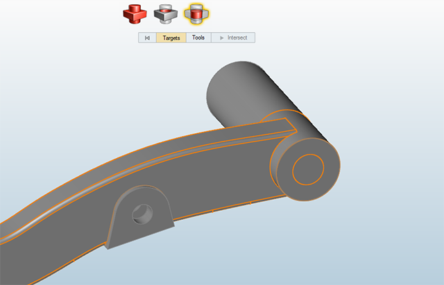
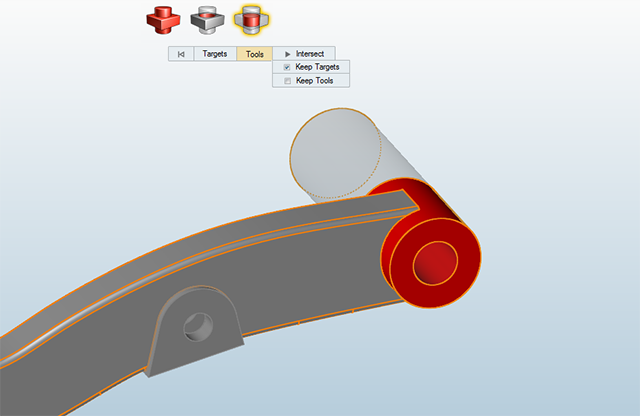
Use Intersection to Create the Primary Cylinder
Select the Boolean tool on the Geometry ribbon.
The Intersect tool is activated, with Targets selected.
Click on the brake arm in the modeling window to select it.
Click Tools on the guide bar.
Click on the primary cylinder in the modeling window to select it.
The Keep Targets check box should already be selected.
Click the Intersect button on the guide bar to perform
the operation.
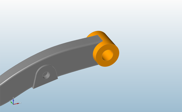
Double-right-click to exit the tool and then select the primary cylinder.
The primary cylinder and the brake arm are now two separate parts.
Use Sketch Tools to Trace a Curve
A third way to duplicate geometry is to sketch over an existing curve using
sketch tools. Adjust the view and use the scroll wheel to zoom in on the
coupling, as shown below:
Select the Circle by Center and Point tool on the
Geometry ribbon.
Click the face of the coupling.
A sketch plane is created perpendicular to the selected face, and the
edges of the face are outlined in red.
Select the New Part icon on the sketching toolbar.
Draw a circle on top of the outer circle of the coupling by clicking once to
place the center point, and again on one of the quad points of the outer
circle.
Double-right-click to exit sketch mode and enter push/pull mode.
Click and drag to extrude the sketch into a solid. Be sure to click inside the
circle so that you select the whole face.
Double-right-click to exit push/pull mode.
Use Intersection to Create the Coupling
Select the Boolean tool on the Geometry ribbon.
The Intersect tool is activated, with Targets selected.
Click on the brake arm in the modeling window to select it.
Click Tools on the guide bar.
Click on the coupling in the modeling window to select it.
The Keep Targets check box should already be selected.
Click the Intersect button on the guide bar to perform
the operation.
Double-right-click to exit the tool and then select the coupling.
The coupling and the brake are now two separate parts.
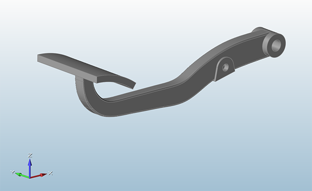
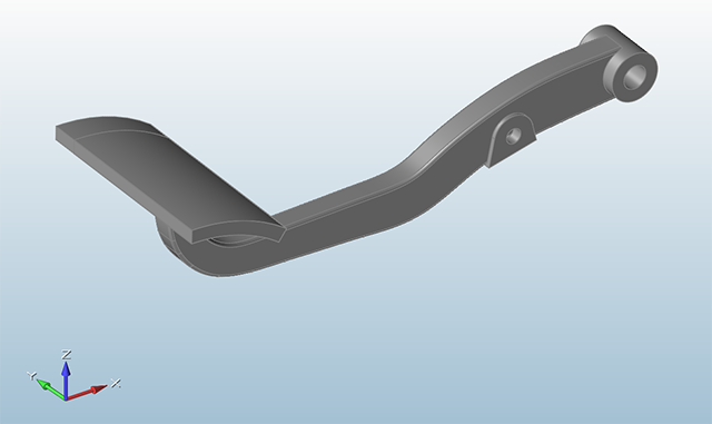
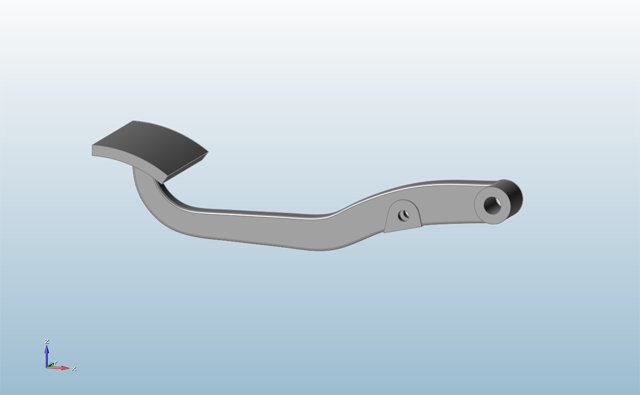
Define a Design Space
Adjust the view so that you can see the entire brake, as shown below:
Click the icon in the view controls at the lower left of the
application to Switch to Perspective Projection.
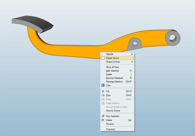
Right-click on the arm of the brake and select Design
Space from the context menu.
Click on empty space.
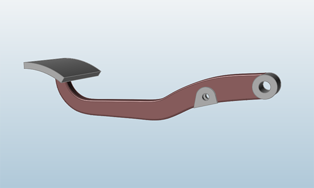
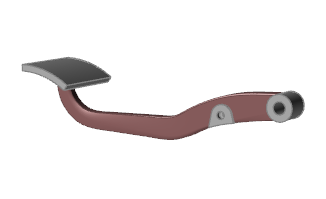
The design space appears reddish brown.
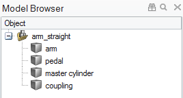
In the Model Browser, rename the brake's parts arm,
pedal, primary cylinder, and
coupling.
Click on a part once in the Model Browser to select it, and again to make the
text field editable.
Click on empty space to deselect all parts.
The imported CAD geometry has now been prepared for optimization, with
the arm of the brake designated as a design space (the part that material will
be carved away from during optimization), while the pedal, primary cylinder, and
coupling have been designated as separate, non-design spaces.
 icon in the lower left corner of the modeling
window to Switch to Orthographic Projection.
icon in the lower left corner of the modeling
window to Switch to Orthographic Projection.
 icon on the sketch toolbar, or right-click one of
the red reference lines and select Create Curves from All Reference
Lines from the context menu.
icon on the sketch toolbar, or right-click one of
the red reference lines and select Create Curves from All Reference
Lines from the context menu.


 icon in the view controls at the lower left of the
application to Switch to Perspective Projection.
icon in the view controls at the lower left of the
application to Switch to Perspective Projection.