Fluid-Structure Interaction Analysis with Radioss and AcuSolve
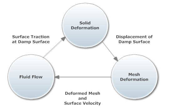
Figure 1. Direct-Coupled Fluid-Structure Interaction (DC-FSI) Cycle
Target Applications
The DC-FSI capability aims at simulations of compliant structural response to fluid flow and its complex interrelationship. This capability is particularly suited for problems exhibiting nonlinear structural response. It may also be used for linear structural response; however, for linear structural response the P-FSI solution offered by AcuSolve may be more effective in solving the linearized structural response with the nonlinear flow solution. For further information on the P-FSI method, refer to the AcuSolve Command Reference Manual. Most Radioss features including nonlinear materials, nonlinear geometric effects, and contact are available for use. The interface domain can be modeled with solid, shell, and beam elements. Most of the features in AcuSolve can be used in DC-FSI simulations. These features may include, namely laminar or turbulent flow, heat transfer, a rich set of material options, free-surface and multi-species driven flows. The moving boundary problems are modeled using Arbitrary Lagrangian-Eulerian (ALE) and sliding mesh technologies. For further details, consult the AcuSolve Command Reference Manual.
- Automotive: Hydraulically damped rubber mounts, door seals, shock absorbers, design of valves and rubber diaphragms and antilock braking systems
- Oil/Gas: Long marine risers, moorings, free spans and drilling risers
- Aerospace: Wing aero-elasticity, UAV and MAV
- Wind turbine: Large deformation of blades
- Consumer Goods: design and packaging
- Bio-medical