OS-V: 0260 Shell Bending under a Tip Load
A beam is analyzed for bending due to tip load. OptiStruct investigates the vertical steady-state displacement at the tip of the beam.
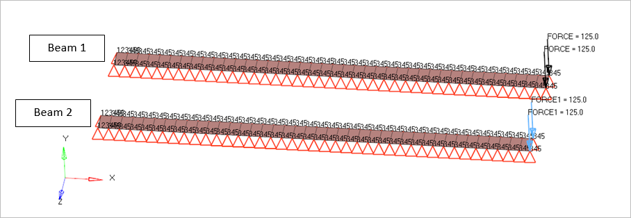
Figure 1.
Benchmark Model
Two Beams are analyzed, Beam1 without follower load and Beam 2 with follower load. Shell elements are used to model the beams which is 400mm long consists of 40 elements and a cross section of 20mm. All the nodes are constrained for the 3,4 and 5 degrees of freedom and the ends of the beams are constrained in all degrees of freedom. Both the beams are loaded at the edge by a point force of 125N on each node in the negative y direction. The load on the Beam1 is not having a follower force whereas the load on the Beam2 is a follower force. Nonlinear static analysis is performed with Large displacement.
- Young's Modulus
- 1000 MPa
- Poisson's Ratio
- 0.0
- Density
- 10000 kg/m3
Nonlinear Static Analysis Results
| Non-Follower Load | y-Displacement (mm) |
Follower Load | y-Displacement (mm) |
|---|---|---|---|
| Bisshopp and Drucker | 240 | Bisshopp and Drucker | 291 |
| CBEAM | 242 | CBEAM | 277 |
| Normalized | 0.99173554 | Normalized | 1.05054152 |
Model Files
The model files used in this problem include:
<install_directory>/hwsolvers/demos/optistruct/verification/Tiploadfllwer.fem
Reference
Bisshopp, K. E., and D. C. Drucker, “Large Deflections of Cantilever Beams,” Quarterly of Applied Mathematics, vol. 3 272, 1945