Compare CAD and Mesh
The native CAD model is imported into HyperMesh along with a user-defined parameter and criteria files. The CAD model is batch meshed and the finite element (FE) mesh created is compared with the CAD model using advanced CAD-FE comparison. A reference report is also created, indicating any change in the meshed profile with respect to geometry.
-
Click the CAD tab then the CAD >
Mesh tab.
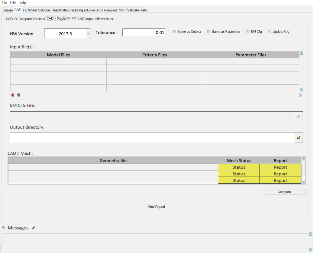
Figure 1. -
Use the Input file(s) section to load a CAD model file(s), parameter file(s)
and criteria files(s).
Tip:
- Click in the cell for each file type to
activate it. Once the cell is active, click
 to
display the file browser and load only selected files. You can also
add multiple files.
to
display the file browser and load only selected files. You can also
add multiple files. - Click
 to add a
row to the table.
to add a
row to the table. - Click
 to
delete a row from the table.
to
delete a row from the table.
- Click in the cell for each file type to
activate it. Once the cell is active, click
Tip:
- The message log file displays the current status of processes in progress. Click Status/Diff to display the respective report. The message log file is a text file and is saved to your output directory.
- Click Html Report to generate an HTML report of your session information for any number of files run through the process.