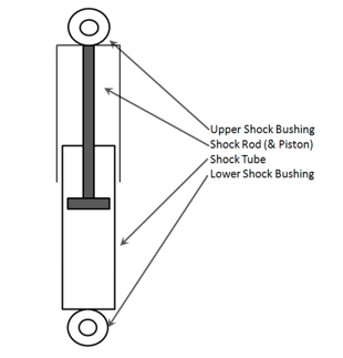
The Shock Absorber system models a conventional shock absorber and the bushings at
the top and bottom of the shock.
The system has is modeled with two rigid bodies, a rod and a tube. Force in the shock
is modeled using the spring damper element in MotionView. Forces generated by the shock are normally a function of the velocity between
the two bodies. Shock data is normally measured on a shock dynamometer. Shock
absorber force is normally non-linear and the extension direction normally generates
more force than the compression direction. A wide variety of shock forces can be
described using the expression builder and the force element found in the shock
absorber system. Figure 1.
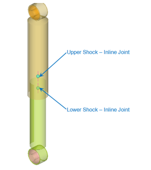
The shock absorber resolves into two different joint types based on the selection in
the Assembly Wizard.
Shock Absorber with Inline Joints
The inline joints represent the joints at the piston to tube location and at the rod
to top of tube location. Figure 2.
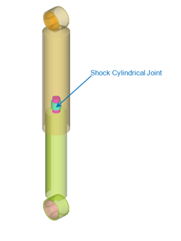
Shock Absorber with Cylindrical Joints
In a cylindrical joint type shock, the two inline joints are replaced with a single
cylindrical joint and located at the top of the shock tube. Figure 3.
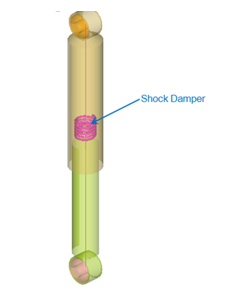
Auto Damper
The AutoDamper is a force-velocity model designed to easily simulate a shock absorber
used in ground vehicles. The damper force generated is positive during compression
and negative during expansion. Figure 4.