HyperForm One-Step analysis can generate a LS-DYNA input file (a dynain file) containing forming results. This effectively allows users to initialize a crash model with forming effects. The preferred quantities to be used for forming initialization are thickness and plastic strains (the stresses are set to zero).
This tutorial features the procedures for preparing an input file for a crash simulation, and illustrates how to:
| • | Perform autotipping on the model |
| • | Perform undercut checking |
| • | Create a dynain file using the HyperForm One-Step solver |
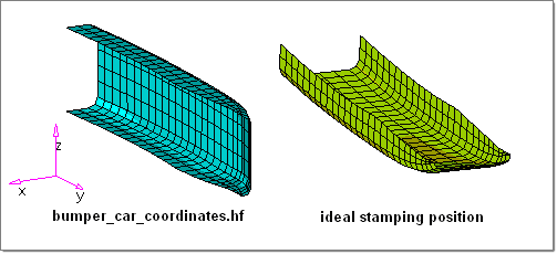
| • | Position the stamped part into a car coordinate position |
| • | Export the stamped part for use in a crash simulation |
This tutorial uses the following panels:
| • | Advanced panel (Dyna/Nastran output option) |
| • | Position tool (Mesh menu) |
Exercise: Transferring Forming Results to Crash Analysis
This exercise uses the model file bumper_car_coordinates.hf.
| 1. | Copy the model files for this tutorial into your working directory. |
| 2. | From the File menu, click Open. |
| 3. | Navigate to the file bumper_car_coordinates.hf. |
Note: The model files for this tutorial are located in the file mfs-1.zip in the subdirectory \hf\1Step\. See Accessing Model Files.
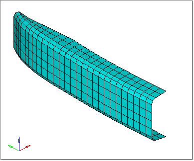
The structure part (bumper_car_coordinates.hf) is not oriented with respect to the stamping direction (z-axis). Prior to running the forming simulation and transferring the forming to the part in a crash simulation, it must be re-oriented with respect to the z-axis. Refer to the image below.
|
| 1. | Click Tools > Autotipping. |
| 2. | Select the autotip subpanel. |
| 3. | Click comps and select the bump_car_co-ord component. |
| 5. | Verify that the toggle is set to full model. |
| 6. | Click calc autotip. The message bar displays the potential rotation angles for autotipping with respect to the stamping direction (z-axis). |
| 8. | Click the F key on the keyboard to fit the model to the screen. |
| 9. | Click return to close the panel. |
|
| 1. | Click Tools > Undercut Check. |
| 2. | Click comps and select the bump_car_co_ord component. |
| 3. | Click the green check undercut button. Notice no elements get highlighted on the screen. The model passes the undercut check and no problems are detected. |
| Note: | A set is created when perform undercut checking. You will delete the set before solving the problem in One-Step analysis. |
|
| 4. | Click return to close the panel. |
| 5. | In the Model browser, expand the Set folder and right-click on the hf_undercut_set set. |
| 6. | Click Delete and select Yes to confirm the action. |
|
| 1. | In this step, you will request output format in LS-DYNA and Nastran solver formats for forming analysis. This allows HyperForm to write out a results file that can be directly used to initialize a structural analysis model. The names for the output files are: |
| - | [filename]_thk.nas and [filename]_dyna.k corresponding to Nastran and LS-DYNA solvers, respectively. |
| - | [filename]_thk.nas contains the mesh data along with the nodal thickness. |
| - | [filename]_dyna.k contains the mesh and the nodal thickness, followed by the stress tensor and plastic strain at each integration point within an element. |
| 2. | Click Setup > Advanced. |
| 3. | Click RADIOSS/Dyna/Nastran output. This option will take you to another panel. |
| 4. | Toggle the option to w/o stress (zero stress will be written to the dynain file). |
| 6. | Click comps again and check the bump_car_co-ord component. |
| 8. | Click return twice to close the panels. |
|
| 1. | From the File menu, click Save As. |
| 2. | Enter the file name as bumper_car_coordinates_complete.hf and click Save. |
|
| 1. | Click Setup > Run Analysis. |
| 2. | Click project: and select bumper_car_co_ordinates_complete. |
| 4. | Click return when the analysis is finished. |
| Note: | Notice several files are generated when 1 step analysis is finished: |
bumper_car_co_ordinates_complete.parm : HFSolver Input deck generated by HyperForm.
bumper_car_co_ordinates_complete_dyna.k : Contains the mesh and the nodal thickness, followed by the stress tensor and plastic strain at each integration point within an element.
bumper_car_co_ordinates_complete_thk.nas : Contains the mesh data along with the nodal thickness.
bumper_car_co_ordinates_complete.out : ASCII output file contains model and run information. This file can be used to debug model and system level problems.
bumper_car_co_ordinates_complete_opt.dat : Input deck for optimization runs with HyperStudy.
bumper_car_co_ordinates_complete.dat : Input data summary.
|
| 1. | Press F2 to open the Delete panel. |
| 3. | Click yes to confirm deletion of model. |
| 4. | Click Applications > Incremental LS-DYNA to change the user profile. |
| 5. | From the File menu, click Import > Solver Deck  . . |
| 6. | Click the folder icon  and browse to the location where the previous analysis was run to select the file bumper_car_co_ordinates_complete_dyna.k. and browse to the location where the previous analysis was run to select the file bumper_car_co_ordinates_complete_dyna.k. |
| 7. | Click Open to select the file. |
| 8. | Click Import to import the file and Close to close the dialog. |
The output file bumper_car_co_ordinates_complete_dyna.k has the identical format as the LS-DYNA DYNAIN file. During the import of the *_dyna.k (dynain) file, only the node and element definitions are read into HyperForm. The initial stress and plastic strain quantities are automatically placed into a new file with an .hmx extension (i.e. filename_dyna.k.hmx) and HyperForm automatically activates an INCLUDE control card to retain the information. More detail regarding DYNAIN file will be discussed in HyperForm incremental analysis.
Notice the warning message "No renumbering or rotation is allowed. Stress and strain history will get written to a .hmx file. Continue?"
If the *_dyna.k (dynain) file contains stress quantities, no rotations of the component are allowed. The stress tensors are written with respect to a global coordinate system, and would require a suitable transformation. In this exercise, because the file contains zero stress, rotations of the component are allowed.
|
In this step, you need to orient the model *_dyna.k file (dynain file) which has the information from the One-Step forming run, back to the car co-ordinate system model for crash analysis. You will first import the original bumper_car_coordinates.hf and re-position forming result in z-axis (*_dyna.k (dynain) file) back to the original vehicle coordinate.
| 1. | From the File menu, click Import > Model  . . |
| 2. | Click the folder icon . In the file browser dialog, switch the Files of Type field to All Files. |
| 3. | Select the bumper_car_coordinates.hf file. |
| 5. | Click the F key on the keyboard to fit the model to the screen. |
| 6. | Click Mesh > Position > Components. |
| 7. | Click the selector and choose comps. |
| 9. | Check the 1 component (import from *_dyna.k file) and click select. |
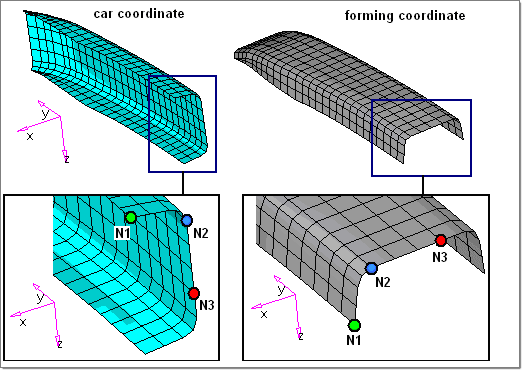
| 10. | Click from: N1, N2, and N3 and select three nodes on the part in forming coordinates (part in gray color) as shown below. |
| 11. | Click To: N1, N2, and N3 and select three nodes on the part in car coordinates (part in blue color) as shown below. |
| Note: | The locations and selection sequence of N1, N2 and N3 nodes in "from" will need to exactly match the corresponding N1, N2 and N3 nodes in "To". This ensures the transformation (consisting of translations and rotations) that maps the differences between the two sets of nodes is applied to the selected entities until they are relocated. |
| 12. | Click position to reorient the stamped part back to car coordinate position. Notice two models are overlapped with each other. |
| 13. | Click F2 to jump to the Delete panel. |
| 14. | Change the selector to comps. |
| 15. | Click comps again and select the bump_car_co-ord component. |
| 17. | Click delete entity. The original part in vehicle is deleted. |
| 18. | Click return twice to go back to the main menu. |
|
| 1. | From the File menu, select Export. |
| 2. | Verify the template field is set to LS-DYNA.key (LS-DYNA template). |
| 3. | Click File: and type the name bumper_crash_input.key. |
| 4. | Click Export and click Close. |
|
| 1. | Open any text editor and load the bumper_crash_input.key file for reviewing. |
Notice:
A. The dyna input file contains the thickness distribution from the One-Step analysis.
*ELEMENT_SHELL_THICKNESS
$ EID PID N1 N2 N3 N4
13 2 12 21 23 14
1.00013 1.00026 1.0004 1.00036
14 2 21 22 24 23
1.00026 1.00045 1.00038 1.0004
15 2 14 23 25 16
1.00036 1.0004 1.00073 1.00097
………………………………
………………………………
B. Plastic strains are carried and included in the *_dyna.k.hmx file
*INCLUDE
[ full path ] / bumper_car_coordinates_complete_dyna.k.hmx
C. bumper_car_coordinates_complete_dyna.k.hmx contains residual strain data from the 1Step forming analysis.
*INITIAL_STRESS_SHELL
*INITIAL_STRESS_SHELL
$ EID NPLANE NTHICK
$ T SIGXX SIGYY SIGZZ SIGXY SIGYZ SIGZX EPS
Where "EPS" is Effective Plastic Strain
D. Forming related control cards need to be deleted/modified accordingly before running the crash analysis
*CONTROL_SHELL
*CONTROL_HOURGLASS
*CONTROL_BULK_VISCOSITY
*CONTROL_CONTACT
*CONTROL_PARALLEL
*CONTROL_ENERGY
*CONTROL_ACCURACY……
|
Return to RADIOSS One Step Tutorials


