A laser-welded blank consists of different thicknesses of metal that has been laser-welded together into a sheet. In addition to achieving direct cost reductions through the more efficient use of materials, tailored blanks also offer manufacturers the potential for greater flexibility in design. Manufacturers currently apply several types of joining processes to weld coated-steel tailored blanks such as seam welding, high-frequency welding, electron beam welding, and laser welding.
In this tutorial you will learn to simulate the welding of two blanks with different thickness and material properties.
To set up the analysis for a laser weld, you need to define two (or more) components in the supplied model. The components may be assigned to different materials and may have different thickness and FLC curves. You use a default FLC curve for one component and create a user-defined FLC curve for another component. In the next step, you will create a sample FLC curve using minor and major strain data.
Exercise: Laser Welded Blank
This exercise uses the model file laser_weld.hf and Laser_weld_FLC_curve.csv.
This tutorial uses the following panels:
|
| 1. | Copy the model files for this tutorial into your working directory. |
| 2. | From the File menu, click Open. |
| 3. | Navigate to the file laser_weld.hf. |
Note: The model files for this tutorial are located in the file mfs-1.zip in the subdirectory \hf\1Step\. See Accessing Model Files.
|
| 1. | From the Setup menu, click FLD Curves. |
| 2. | Click the library subpanel. |
| 3. | Click file = and select Laser_weld_FLC_curve.csv. |
The figure below shows the FLD curve panel.
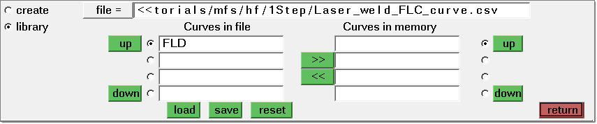
On the left-hand side of the panel, under Curves in file, the name of the curve (FLD Curve) should appear.
| 4. | Click  to transfer the FLD curve to memory. to transfer the FLD curve to memory. |
The name FLD Curve should appear beneath Curves in memory.
| 5. | Click return to exit out of the FLD Curve panel. |
|
| 1. | Click Mesh > Organize > Elements > To Component and select the collectors subpanel. |
| 2. | Click elems and select by windows from the pop-up menu. |
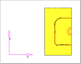
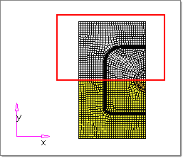
| 3. | Draw a window on the graphics area to include the top half of the elements of the entire model. Refer to the image below. |
| 4. | Click select entities. Notice the elements within the window are highlighted. |
| 5. | Click Dest Component = and select comp1. |
| 6. | Click move. All selected elements are moved and stored in the comp1 component. |
| 7. | Repeat steps 1-6 and relocate lower elements into the comp2 component. |
|
| 1. | Click Setup > Components. |
| 2. | Click component: and select comp1. |
| 3. | Click material and select CRDQ steel. |
| 4. | Click thickness = and type 1.0. |
Notice the message bar shows "The component has been updated." You have associated the comp1 component with the CRDQ steel material and a thickness of 1.0.
| 6. | Repeat steps 1 - 5 and re-associate the comp2 component, as shown in the table below: |
Component 1
|
Component 2
|
Name : comp1
Material : CRDQ Steel
FLD curve : Default_FLC (Blank)
Thickness : 1.0
Color : color green
|
Name : comp2
Material : Steel 1
FLD curve : FLD curve
Thickness : 2.0
Color : color blue
|
| Note: | comp1 is assigned the Default_FLC curve (blank) and comp2 is assigned the user defined FLD curve. |
|
|
| 1. | From the File menu, click Save As. |
| 2. | Browse for a user defined location and name the file as laser_weld_complete.hf and click Save. |
| 3. | From the Setup menu, click Run Analysis. |
| 6. | From the Utility menu, under Results, use all the functionalities for reviewing results. |
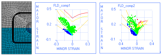
| 7. | Review the results of the laser-welded blank. |
|
Return to RADIOSS One Step Tutorials


