This feature allows you to track a line between the stamped part and the initial undeformed blank to minimize material waste (part to blank). It also allows you to map trim lines between the intermediate stages of stamping such as between the final flanged stage and the prior drawn stage (part to part).
The tutorial is divided into two exercises:
Exercise 1: Trimming the Line Layout
In this exercise, you will study the difference between the final part to the undeformed blank and generate IGES data for a trim line selected from the part and mapped onto original blank.
Exercise 2: Mapping the Trim Line from Final Part to Intermediate
The purpose of the part-to-part line mapping is to allow you to map a line (or node list) between a final part and an intermediate part.
This tutorial uses the Line Mapping panel.
This exercise uses the model file part_blanktrimline.hf.
| 1. | Copy the model files for this tutorial into your working directory. |
| 2. | From the File menu, click Open. |
| 3. | Navigate to the file part_blanktrimline.hf. |
Note: The model files for this tutorial are located in the file mfs-1.zip in the subdirectory \hf\1Step\. See Accessing Model Files.
|
| 1. | From the File menu, click Save As. |
| 2. | Browse for a user defined location and name the file as part_blanktrimline_complete.hf and click Save. |
| 3. | Click Setup > Run Analysis. |
| 4. | Click run analysis. HyperForm solves the analysis. |
| 5. | When the analysis is finished, click load results. |
| 6. | Click return to close the panel. |
|
| 1. | From the main panel area, select the Line Mapping panel and the part to blank subpanel. |
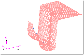
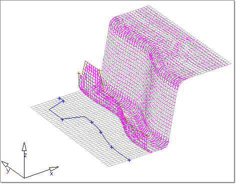
| 2. | Click line and select the line on the final part shape as shown in the figure. |
Note: This line is the one that will be mapped on to the flat blank.
| 3. | Click comps and select final_part as your flange part:. |
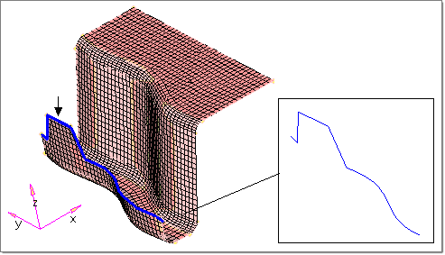
| 4. | Click initial to display the original points with respect to the undeformed blank. |
| 5. | Click return to close the panel. |
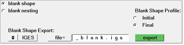
Note: The trim line can be exported as IGES data externally.
|
|
This exercise uses the model file part_parttrimline.hf.
The purpose of the part-to-part line mapping is to allow you to map a line (or node list) between a final part and an intermediate part. This method can be useful for predicting where a part should be trimmed prior to a flanging operation.
For example, if you have a part that is made using three operations (1st draw, trim, and 2nd draw), and you want to predict where the flange line should be trimmed prior to the 2nd draw, you can use the line mapping (part to part) feature. To do this, you will need to model the part shape at the end of the 1st draw (intermediate shape) and at the end of the 2nd draw (final shape). Both of these parts should be modeled in the same HyperForm file. After performing the 1Step analysis and loading the results file, the line mapping function can be used. The flange line should be defined on the final shape and trim part elements should belong to the intermediate part.
| 1. | From the File menu, click Open. |
| 2. | Browse the to file part_parttrimline.hf. |
|
| 1. | Click Setup > Components to review the two components. There are two components that represent the intermediate and the final part. |
| 2. | (optional) Click the letter D to open the Display panel. Change the entity selection to loadcols to see how the parts have been constrained. This prevents the parts from moving with respect to each other. |
|
| 1. | From the File menu, click Save As. |
| 2. | Browse for a user defined location and name the file part_parttrimline_complete.hf and click Save. |
| 3. | Click Setup > Run Analysis. |
| 5. | When the analysis is finished, click load results. |
|
| 1. | From the main panel area, select the Line Mapping panel and select the part to part option. |
| 2. | Pick the nodes or line you want to map as your flange line. |
You can select the line in the ^feature component.
| 3. | Click trim: comps and select the intermediate_part component. |
| 4. | Click flange part: comps and select final_part component. |
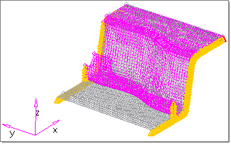
| 5. | Click map. A mapped line is generated and stored in the ^Mapping_line component. |
Line mapping Part to Part
|
|
Return to RADIOSS One Step Tutorials


