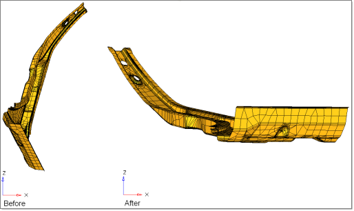
Undercut is a term used in part design that refers to situations that lead to die lock condition when the part is being formed. In real-time forming applications, parts are designed in such a way that they get locked if formed. Split dies and punches with negative rake angles are used to form such parts to avoid this situation. But for the simulation purpose in One-Step analysis, the part is tilted in such a way that the Z-axis of the part matches with the Z-axis of the punch and the die. This process of aligning the part axis with the tool axis is called Autotipping. The angle to be tilted is calculated automatically by HyperForm.
| • | Stamping can also be done in any of the three principal axes or an arbitrary axis in space by using the stamping direction subpanel in the Autotip panel. |
| • | The autotipping option will reduce the draw depth by making the z-axis as the stamping direction. |
In this tutorial you will learn to check for undercut and remove it in a part by using the Autotip feature.
This tutorial assumes that you are familiar with functionalities such as creating components, geometry cleanup, and meshing. Information on these topics can be found in the online help.
Exercise: Undercut checking and Autotipping
This exercise uses the model file mesh_quality.hf.
The tools used in this tutorial can be found in the RADIOSS One Step user profile.
Autotipping
Allows you to set the user defined stamping direction for the part. It can also help you to tip (orient) the part in the formable position along the user defined stamping direction.
Undercut check panel
Allows you to identify all the elements in the displayed part that may lead to a die-lock condition. The stamping direction is assumed to be along the global z-axis.
|
| 2. | Navigate to mesh_quality.hf. |
Note: The model files for this tutorial are located in the file mfs-1.zip in the subdirectory \hf\1Step\. See Accessing Model Files.
|
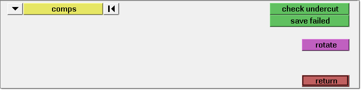
| 1. | Click Tools > Undercut Check. |
| 2. | Click comps and select the mesh component. |
Notice that the header bar displays the number of elements with an undercut problem. Any element detected with an undercut problem is highlighted on screen. You can click saved failed and save the undercut elements into a user mark to be retrieved and fixed later.
In One-Step analysis, minor undercut problems occurring at non-critical areas are unavoidable and acceptable. When significant undercut is detected, Local bending/Unbending in the Advanced panel is automatically disabled for better result accuracy.
In this exercise, the undercut problem is not severe and therefore you will leave the model as it is.
|
| 1. | Click Tools > Autotipping. |
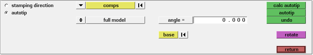
| 2. | Select the autotip subpanel. |
| 3. | Verify the entity selector is set to comps and select the mesh component. |
| 4. | Verify the toggle is set to full model and keep the rest of the options as default. |
| 5. | Click calc autotip. Notice the angle to be tilted is displayed on the header bar. |
| 6. | Click autotip. This action will tilt the part by an angle calculated by HyperForm to avoid the die lock situation during forming. The default tipping direction would be +Z. Click F to fit the model to the screen if the display is not desirable. |
|
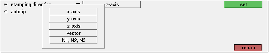
| 1. | Click the stamping direction radio button. |
| 2. | Click on the vector selector and select the N1 N2 N3 option. |
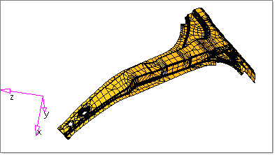
| 3. | Click on any 3 nodes as shown below along the tail of the part and click set. |
| 4. | Open the autotip subpanel. |
| 5. | Verify the entity selector is set to comps and select the mesh component. |
| 6. | Verify the toggle is set to full model and keep the rest of the options as default. |
| 7. | Click calc autotip. The angle of orientation is displayed on the header bar. |
Note: Similarly the tool tipping can performed as per the user specific requirements.
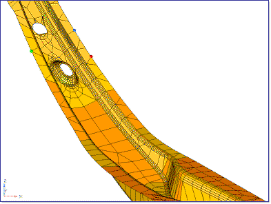
N1 N2 N3 node selections
|
Return to RADIOSS One Step Tutorials


