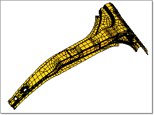
It is always a good practice to check the quality of the mesh before running the analysis. HyperForm allows you to check different quality criteria such as conformance to the surface topology, Jacobian, warpage, length, skew angle, etc. Conformance to surface topology is a visual check that ensures that the mesh lies on the surface and none of the elements are warped. Checks should be done to ensure that features are being reasonably captured (fill plot check). Mesh connectivity is equally as important. This can be checked using the edge check macro.
In general, the below element quality will be satisfied to acquire better analysis result accuracy:
| • | Remove duplicate elements |
| • | Avoid zero-length elements (recommended value larger than 0.1) |
| • | Warpage is recommended to be less than 30 |
| • | Larger Jacobian values are better. No negative Jacobian value is allowed. It is recommended to have a Jacobian value larger than 0.1. |
Exercise: Mesh quality checking and improving
This exercise uses the model file mesh_quality.hf.
The tutorial uses the Element Quality Report module and the following menu options:
| - | Elements > Check Elements |
| - | Elements > Quality Index |
| - | Elements > Combine Elements |
| - | Elements > Split Elements |
|
| 2. | Navigate to the model file mesh_quality.hf. |
Note: The model files for this tutorial are located in the file mfs-1.zip in the subdirectory \hf\1Step\. See Accessing Model Files.
|
| 1. | From the Utility menu, under Model, click on Check Elems. |
| 2. | Click Quality Report. The 2D Element Quality Report dialog appears. The Quality Report Tool will check all the 2D elements regardless of whether they are displayed on or off. |
| 3. | Modify the following values: |
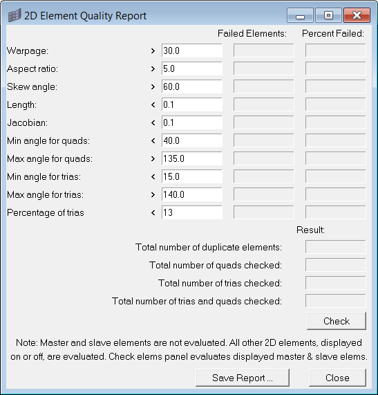
Warpage > 30.0 => # of failed Elems = ______________
Length <0.1 => # of failed Elems = ______________
Jacobian < 0.1 => # of failed Elems = ______________
| 5. | Click Close to close the dialog. |
|
| 1. | Click Mesh > Check > Components > Edges. |
| 2. | Ensure the comps button is highlighted and graphically pick any element to select the component. |
| 3. | Set the tolerance = 0.01 and toggle to find: free edges. |
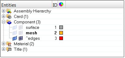
| 4. | Click find edges. HyperForm generates a new ^edges component. Notice red 1D edge elements are generated along the free boundary. |
| 5. | Using the Model browser, expand the Component folder and uncheck all geometry except the ^edges component. |
You should see only the red lines for the free mesh boundary. In the next step, you will find elements attached to the ^edges elements to visually verify this.
| 6. | Click return to close the panel. |
| 7. | Click Shift + F5 to open the Find Attached Entities panel. Select the find attached subpanel. |
| 8. | Click elems >> displayed. |
| 9. | Click find. Repeat steps 8 and 9 again to find 2 layers of elements attached to the edge elements. |
Note: Two layers of elements attached to ^edges elements are displayed back on screen. You can click Find Attached more times to find more layers of elements. Any missing holes or elements can be indication of connectivity problems. This method can be used to localize the disconnecting areas.
| 10. | In the Model browser, right-click on the Component folder and select Hide to turn off the display of all components. |
| 11. | Right-click again and select Show to display all components back on screen. |
| 12. | Click return to go back to the main menu. |
| 13. | In the Model browser, right-click on the ^edges component and select Delete. |
| 14. | Click Yes to confirm the action. |
|
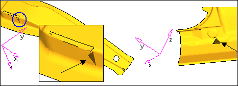
In this step, you will use the split subpanel to manually fix an element quality problem. Four methods used to split elements free-form are illustrated below.
HyperForm prompts you to build a line to split these elements using one of the four methods. Draw a window as shown in the figure below.
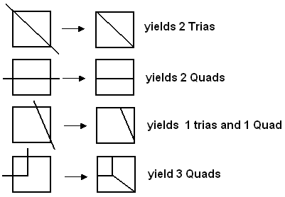
Types of element splits
| 1. | On the keyboard, click V and click restore1 to retrieve a saved view. |
| 2. | Click the F6 key to access the Combine Elements panel. |
| 3. | Select the split subpanel and change the selector from displayed elems to elems. |
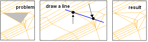
| 4. | With elems activated, graphically select the element as indicated in the image below. |
| 5. | Under Splitting line:, click points to draw a line passing through two nodes (two black circles in the image) of the selected element. Refer to the image below. |
| 6. | Click split to split the element. |
|
| 1. | Click F10 to open the Check Elements panel. |
| 2. | With 2-d selected, click duplicates to check if there are any duplicated elements. The message bar displays "0 duplicate elements were found". If any duplicate element is identified, it will be highlighted. |
| 3. | Click length. The message bar warns that the minimum length is larger than 0.0. Any element with length equal to or less than 0.0 must be fixed. |
| 4. | Click jacobian. The message bar warns that the minimum length is larger than 0.0. Any element with Jacobian value equal to or less than 0.0 must be fixed. |
| 5. | In the warpage field, enter 30.0. |
| 6. | Click warpage. Notice that the message bar displays "25 of 4668 (1%) failed. The maximum warpage is 176.01." |
| 7. | Click save failed to store the failed elements (warpage > 30.0) into a user mark. The message bar displays "The highlighted elements have been placed in the user mark". |
| 8. | Click return twice to close the panels. |
| 9. | In the Model browser, right-click on the Component folder and select Hide. |
| 10. | Press Shift+F5 on the keyboard to open the Find panel. |
| 11. | Open the find entities subpanel. Click elems and select retrieve to retrieve elements from the user mark. The message bar displays "25 elements added by ‘retrieve. Total selected 25". |
| 12. | Click find to display the 25 elements on the screen. Elements with warpage >30.0 are displayed on the screen. |
| 13. | Press the F key to fit the model to the screen. |
| 14. | Click return to close the panel. |
|
| 1. | Click Shift+ F6 key to open the Edit Elements panel. |
| 2. | In the plate elements subpanel, click the selector to change from split all sides to divide quads. |
| 3. | Click elems >> displayed. |
| 4. | Click split. The displayed quad elements are divided into trias elements. |
| 5. | In the Model browser, right-click on the Component folder and select Show. |
|
| 1. | Click Mesh > Check > Elements > Quality Index. |
| 2. | Under pg1 (page 1), uncheck max size, aspect ratio and skew. |
| 3. | Under threshold, input min size = 0.1 and warpage = 30.0. |
| 4. | Click  right next to pg1 and change to pg2. right next to pg1 and change to pg2. |
| 5. | Uncheck all features EXCEPT # of trias. |
Notice elements with color on screen indicate they fail to satisfy the activated quality check.
Quality Index function allows element's quality to be improved by node optimize method and element optimize method.
| - | For node optimize method, click node optimize and select a node on the screen. HyperForm repositions the node on the inferred surface to obtain the best possible quality for all elements attached to that node. |
| - | For element optimize method, click element optimize and select an element on the screen. The locations of all its nodes move on the inferred surface to obtain the best possible quality for that element and its neighbors. |
In this, you will leave Jacobian = 0.3 .
| 6. | On the keyboard, click V and click restore 3 to retrieve a saved view. |
| 7. | Click node optimize and graphically pick the node as indicated in the image below. |
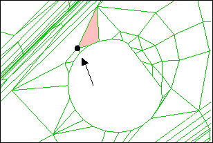
Notice the selected node is relocated and element quality is improved. The associated element is also changed to transparent mode.
|
| 1. | Click Applications > RADIOSS One Step. |
| 2. | From the Utility menu, under Model, click on Check Elems. |
| 3. | Click the Quality Report macro. |
| 6. | Compare the values to the ones written in step 3. |
| 7. | Click Close to close the dialog. |
|
Return to RADIOSS One Step Tutorials