|
»Click here to display Table of Contents«
|

HF-0300: Automeshing |

|

|

|

|
|
HF-0300: Automeshing |
|
|

|

|
|
»Click here to display Table of Contents«
|
HF-0300: Automeshing |
|
|
|
|
|
HF-0300: Automeshing |
|
|
|
|
This tutorial introduces you the variety of meshing capabilities available in HyperForm.
| • | BatchMesher |
| • | AutoMesh |
| • | R-Mesh (available in RADIOSS One Step, Incremental_LS-DYNA and Incremental_RADIOSS user profiles) |
| • | B-Mesh (only available in the Incremental_RADIOSS and Incremental_LS-DYNA user profiles) |
The BatchMesher is an external tool that can perform geometry feature recognition, cleanup and automatic meshing (in batch mode) for given CAD files without user interaction. Detail of the BatchMesher will not be discussed in this tutorial. Refer to the HyperWorks online help for more information about BatchMesher. In this tutorial, you will be introduced to the three meshing modules: AutoMesh, R-Mesh and B-Mesh.
In HyperForm, most of the element creation panels use the AutoMesh module, which supplies as much automated assistance as possible. AutoMesh allow you to adjust mesh interactively with a wide variety of parameters and choose from a suite of algorithms. You can interactively control the number of elements on each edge or side and you can immediately determine the nodes that are used to create the mesh. You can adjust the node biasing on each edge to force more elements to be created near one end than near the other, which allows you to see immediately the locations of the new nodes. The new elements can be specified as quads, trias, or mixed and can be first or second order elements. The created mesh can be previewed, which allows you to evaluate it for element quality before choosing to store it in the HyperMesh database. While you are in the meshing module, you can use any of viewing tools on the visual options menu to simplify the visualization of complex structures in your model. You can also re-mesh existing meshing interactively or automatically on surfaces or groups of elements. You will learn to use a variety of AutoMesh features later in this tutorial.
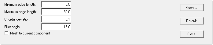
R-Mesh (Rigid tool surface mesh) allows you to quickly mesh a rigid tool surface by specifying the max length of element, minimum length of element, chordal deviation, and fillet angle.
B-Mesh (Blank surface mesh) allows you to quickly mesh a blank component. You can specify an average edge length and mesh selected surfaces. B-mesh is discussed in incremental analysis tutorials.
Bpillar_AutoMesh.hf
Bpillar_AutoMesh_remesh.hf
Bpillar_AutoMesh_remesh_final.hf.
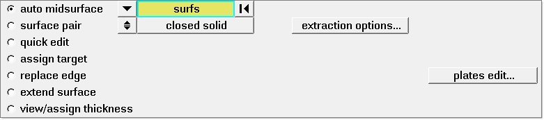
The tools in this tutorial can be found in the RADIOSS One Step user profile. MidsurfaceThe Midsurface panel allows you to extract the midsurface representation of a solid part.
AutoMeshThe AutoMesh panel allows you to create meshes or re-mesh existing meshing.
R-mesh macroRapidly generates a quad/tria shell mesh ideal for representing rigid tool surfaces.
|
Note: The model files for this tutorial are located in the file mfs-1.zip in the subdirectory \hf\1Step\. See Accessing Model Files. |
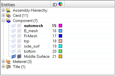
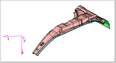
Notice the color of the model is changed and topology definitions are displayed on screen.
The model is a pre-cleanup geometric model with thickness. In reality, it is common to have CAD data with thickness. You will learn how to extract midsurface in the next steps.
Midsurface extraction takes about one to four minutes depending on system performance. Notice that once the operation is finished, a new component named Middle Surface is created that contains the extracted midsurface. By default, HyperForm applies the transparent view to the generated midsurface.
|
|
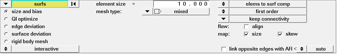
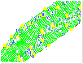
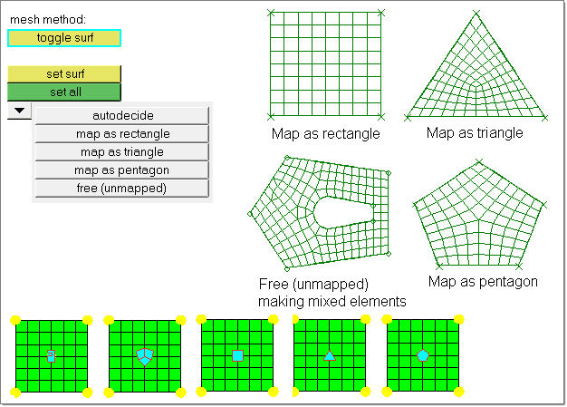
In this step, you will learn how to interactively mesh a blank using size and biasing control. The size and bias subpanel allows you to mesh surfaces or re-mesh existing meshes with some control over how the mesh is created. You can also adjust a mesh on-the-fly during the creation process using this subpanel.
element size = 3.0 mesh type = mixed elems to current comp toggle is set (generated elements will be stored in the current working component automesh component) first order toggle is set next to map: the size and skew checkboxes should be selected Toggle is set to interactive
Notice a mesh is displayed in the graphics area. You have entered the Automeshing Secondary panel (inactive mesh module), which allows you to manually adjust mesh before it is finalized.
Refer to the following images:
Notes: calculate: edge allows you to interactively modify individual edge or all edges based on desired element size. set: allows you to interactively modify individual edges or all edges based on a specified value.
Mesh style allows you to specify the meshing and smoothing algorithm to use for each face of each domain when you are following a surface-based approach to the Automeshing Secondary panel.
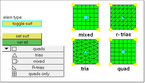
Notice all the element type symbols are changed to tria. Refer to the image below.
Notice the mesh type and symbol is changed to trias.
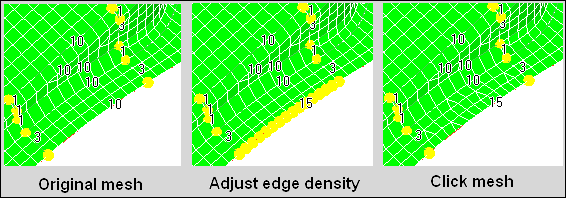
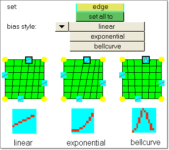
Biasing allows you to control the element density biasing along edges. Element biasing is the placing of elements along an edge so that element size is smaller at one end than at the other, and is one way to improve element quality when doing transitioning. By default, all mesh edge biasing is linear with value 0.0. You can change the biasing style and increase/decrease biasing factor by left-/right-clicking on the edge biasing numbers. The following image shows different biasing styles.
|
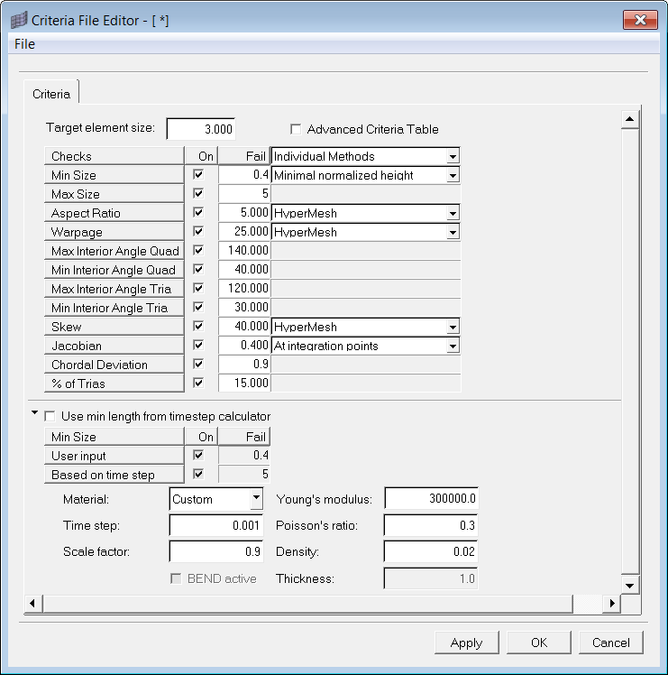
In QI optimized meshing, the surfaces are meshed to optimize the quality index (QI) of the elements generated. You can either provide a criteria file or update the Quality Index panel with the desired quality criteria. The surfaces are then meshed with algorithms that produce the best quality index. The placement of the nodes on the surface is also optimized to improve the QI.
|
The edge deviation subpanel allows you to set specific meshing parameters to limit how far the mesh elements can deviate from the actual edges of the surfaces meshed. The edge deviation normally occurs on curved edges, because individual elements have straight edges and therefore can only approximate a curve. This automesh sub function automatically chooses the best element size to approximate a curve, within limits that you specify. Note that this differs from the size and bias subpanel, which only meshes with elements of a uniform size that you specify.
|
Similarly to the edge deviation subpanel, meshing behavior on this subpanel is driven by distances between flat elements and model geometry. When HyperMesh uses flat elements to approximate a curved surface, there is always a discrepancy between each element and the actual curve of the surface, because the element uses a straight line between two nodes. The surface deviation automesh method chooses the mesh density based on the severity of this deviation. Where the threshold deviation would be exceeded, HyperMesh uses a larger number of smaller elements to reduce the deviation. For more information, please refer to the online help.
|
Rigid bodies are surfaces that are expected to impact other model surfaces, but are rigid enough that they themselves are not expected to deform as a result of the impact. When modeling the results of a stamp pressing down on a metal sheet, it’s important to model the shape of the stamp because that determines the shape of the metal sheet after being pressed. However, it is not important to model the stresses placed upon the stamp tool. Therefore, the mesh quality of rigid tooling is less important in the comparison of the captured shape of the tools. The R-Mesh macro directly accesses the AutoMesh/rigid body mesh feature. You can find the R-Mesh macro under both the RADIOSS One Step and Incremental_RADIOSS user profiles.
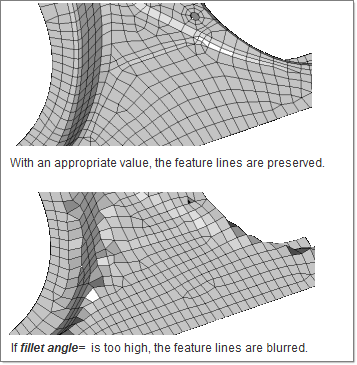
Note: The fillet angle field is used to specify a maximum angle across which elements can be maintained. If at any time two adjacent elements’ normals would exceed this angle, HyperForm creates a new set of nodes between them to maintain clean feature lines. Using a higher value would result in nodes spanning along the feature line.
|
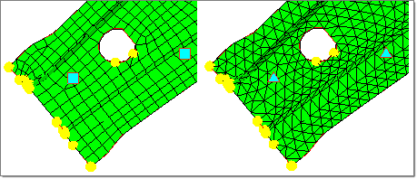
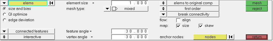
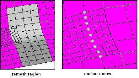
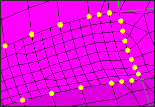
AutoMesh enables you to re-mesh elements. In HyperForm, you can remesh elements when no geometry exists. The remeshing function is activated when you switch the entity selector from surfs to elems. Elements are remeshed with the use of the HyperMesh inferred surface algorithm, if geometry for the selected elements needs to exist in the model. The inferred surface algorithm interpolates geometry data from the selected elements in order to create new mesh. When elements are selected to be remeshed, there is the break connectivity option and the vertex angle parameter. The break connectivity option detaches the node connectivity between adjacent selected and unselected elements. This allows you to adjust the node densities along the boundary of the selected elements. The vertex angle parameter defines the placement of vertices along the boundary of the selected elements. If the angle between two adjacent element edges along the boundary is less than the specified angle, a vertex is placed at the meeting point of the two edges. Anchor nodes create the effect of a fixed point on the inferred surface (which is derived from the existing mesh) and keep the location of the anchor nodes intact.
Also verify that all the settings are as shown in the image below:
You are still in the Mesh panel.
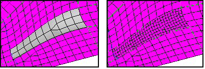
In the next few procedures, you will rebuild the mesh’s transitional region by re-meshing elements with applied anchor nodes.
|
To ensure connectivity between the elements, you need to equivalence any coincident nodes in the model. The equivalence operation identifies any location where two or more nodes exist within the specified search tolerance. During equivalence, one of the nodes is retained, and any element definitions referencing the other nodes are re-defined to use the retained node.
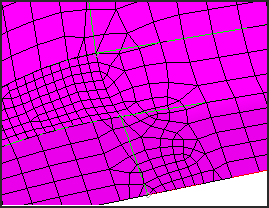
You have fixed the connectivity problem of one side of the refined region. The remaining connectivity problems can be fixed using the same technique. For the purposes of this tutorial, you will load the final result for reviewing directly.
|