In this exercise, you will use a variety of tools to fix geometry problems.
Step 1: Remove pinholes using the Auto Cleanup panel
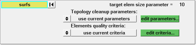
| 1. | From the Geometry menu, select Autocleanup. |
| 2. | Click edit parameters to launch the Parameters File editor to modify Auto Cleanup settings. |
| 3. | In the Parameters File editor, clear all settings under Other options. |
| 4. | Click the  next to Other options and change to next to Other options and change to  . This disables the other options. . This disables the other options. |
| 5. | Repeat the steps above and disable all options EXCEPT Geometry cleanup and Surface hole recognition. |
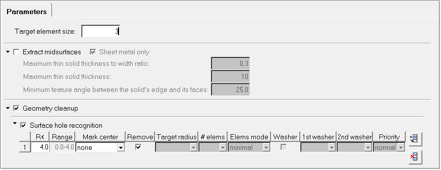
| 6. | Click  (Delete line) to delete the second row under Surface hole recognition. (Delete line) to delete the second row under Surface hole recognition. |
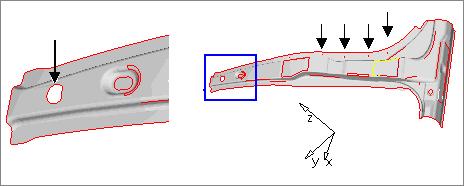
| 7. | In the first row under Surface hole recognition, input 4.0 under R< and check Remove. The final result should look like the image below. Since the largest diameter of the holes on the flange is about 3.2, using the value 4.0 can make sure all the holes on the flange will be removed. |
| 8. | Change Target element size: to 3.0. The target element size is the desired mesh size after geometry cleanup. |
| 9. | Click Apply and Ok to return to the Auto Cleanup panel. |
| 10. | Click surfs >> all from the pop-up window. |
Notice the cleanup process is launched. A message is displayed "There is a conflict between the user requested element size of 3 and the quality criteria ideal element size 0.5 used in the optimization, How do you wish to proceed?"
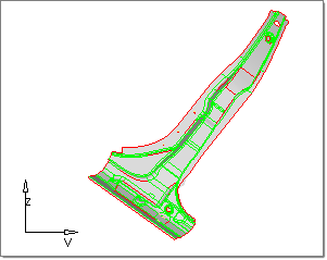
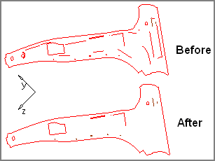
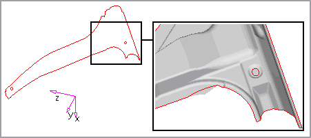
When the cleanup process is finished, a message "Geometry cleanup process is finished" is displayed in the status bar. After the auto cleanup process, notice that:
| • | The four holes on the flange are removed. |
| • | The number of free edges (red edges) is reduced as shown in the image below. If you wish to see only the free edge definitions, select the Visualization  icon and deactivate all topologic definitions EXCEPT Free edges. icon and deactivate all topologic definitions EXCEPT Free edges. |
| • | Duplicate surfaces are removed. |
| 13. | Click return to close the Auto Cleanup panel. |
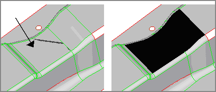
Step 2: Fix the missing surface using the Quick Edit panel
In this step, you will manually clean up geometry using the Quick Edit panel.
| 1. | From the toolbar, select the Visualization icon and activate all topologic definitions. |
| 2. | From the toolbar, click the Shaded Geometry & Surface edges icon  to shade surfaces. to shade surfaces. |
| 3. | Click v on the keyboard to open the dialog with saved views. |
| 4. | Click restore 1 to withdraw previously saved missing surf view. |
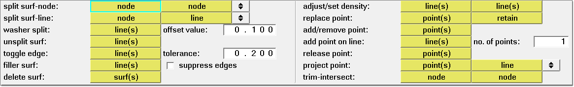
| 5. | Click F11 to access the Quick Edit panel. |
| 6. | Click the line(s) button right next to filler surf:. A blue halo appears and surrounds the line button. |
| 7. | Click any red edge of the missing rectangular surface. A surface is created to fill the missing surface. Notice the previous four free edges are now changed to a green shared edge. |
| 8. | Click return to close the panel. |
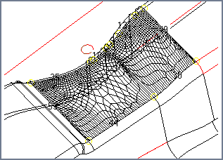
Step 3: (optional) Delete the distorted surface and recreate it
Using the Auto Cleanup function, most of the time, distorted surfaces are removed automatically. If you do not see distorted surfaces after the Auto Cleanup operation, skip this step.
| 1. | Click v on the keyboard to open the dialog with saved views. |
| 2. | Click restore 2 to display the previously saved distorted surf view. |
| 3. | Press F2 on the keyboard to go to the Delete panel. |
| 4. | Click the entity selector and change it to surfs. |
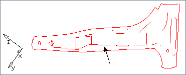
| 5. | Click surfs and select the distorted surface (the surface with dark shadow) from the screen. |
| 6. | Click delete entity. This action deletes the distorted surface. |
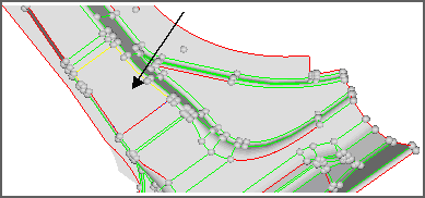
| 7. | From the menu bar, click Geometry > Create > Surfaces > Ruled. |
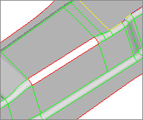
| 8. | If necessary, click the switch to set the selection to line list. Click the upper line list selector and select the three red edges, as shown in the image below. |
| 9. | Click the lower line list selector and select the one red edge, as shown in the image below. |
| 10. | Verify that Auto reverse is activated. |
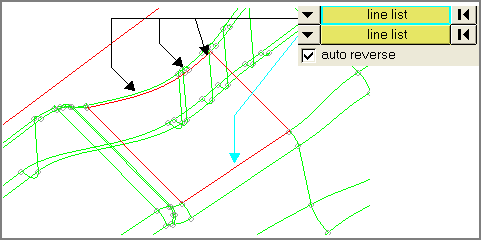
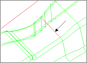
Notice a new surface is created at the same location. The new surface has three shared (green) edges and one free (red) edge as indicated in the image below.
| 13. | Press the F11 key to open the Quick Edit panel. |
| 14. | Click the line(s) button right next to toggle edge:. |
| 15. | Change the tolerance to 0.1. This is the geometric cleanup tolerance. |
| 16. | Use the left mouse button to click the red free edge to turn it into a shared green edge. |
| 17. | Click return to close the panel. |
Step 4: (optional) Delete the duplicated surfaces
Using the Auto Cleanup function, most of the time, duplicated surfaces are removed automatically. This step is optional if you wish to remove duplicated surfaces manually without Auto Cleanup. If you don’t see duplicated surfaces after the Auto Cleanup operation, skip this step.
| 1. | Click Geometry > Defeature. |
| 2. | Select the duplicates subpanel. |
| 3. | Change the entity selector from surfs to faces. |
| 4. | Click faces and select all from the pop-up window. |
| 5. | Click find. Notice two duplicated surfaces are highlighted and identified. |
| 6. | Click delete to remove the duplicated surfaces. |
| 7. | From the toolbar, select the Visualization icon . |
| 8. | From the Visualization tab, select the Topology icon and uncheck Shared, Suppressed and Non-manifold to turn off the display of all definitions EXCEPT free edge (red line). |
| 9. | From the toolbar, select the Wireframe Geometry icon  . . |
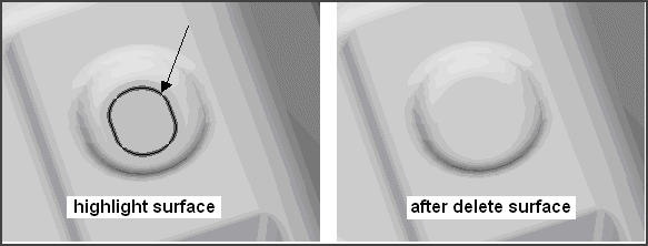
Notice a red circular line indicating free edge. Since there is no hole existing, it indicates a problem with redundant surface.
| 10. | From the toolbar, click the Shaded Geometry & Surface edges icon to shade surfaces. |
| 11. | Press F2 on the keyboard to go to the Delete panel. |
| 12. | Change the entity selector to surfs. |
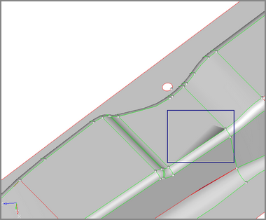
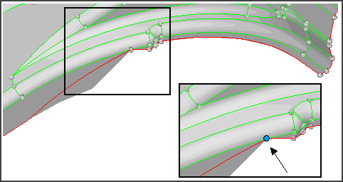
| 13. | Hold the left mouse button and move the cursor to the red circular line until the circular surface edge is highlighted. Let go of the left mouse button and click delete entity to delete the surface. Refer to the image below. |
| 14. | Click return to close the panel. |
| 15. | From the toolbar, select the Visualization icon . |
| 16. | Check Shared, Suppressed and Non-manifold to turn on the display of all definitions. |
Step 5: (optional) Relocate a shared edge
Using the Auto Cleanup function should have relocated this edge. If you do not see this edge after the Auto Cleanup operation, skip this step.
| 1. | Click v on the keyboard to open the dialog with saved views. |
| 2. | Click restore 3 to display the previously saved improve share view. |
| 3. | Click F11 to access the Quick Edit panel. |
| 4. | Click the Points panel right next to replace points:. The function is activated. |
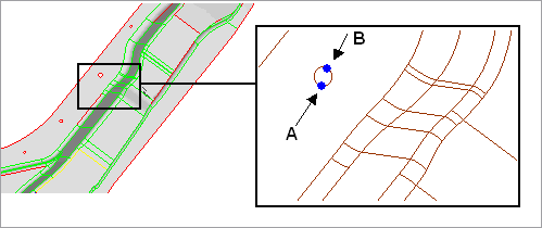
| 5. | Click points and click the fixed point B as shown in the image below |
| 6. | Click retain and click the fixed point A as shown in the image below. |
Notice the two fixed points are now merged. Point B is moved to point A.
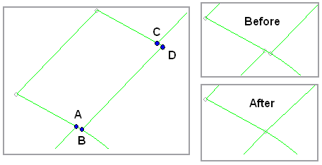
| 7. | Repeat steps 5 and 6 to merge point C and point D by moving point D to the location of point C. |
Step 6: Fix the incorrect fixed point
| 1. | Click v on the keyboard to open the dialog with saved views. |
| 2. | Click restore 4 to display the previously saved fixed point view. |
| 3. | Click point(s) for release point to activate this feature. |
| 4. | Click the fixed point, as indicated in the image below. |
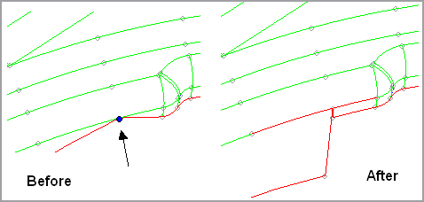
Notice the fixed point is released and some free edges are generated.
| 5. | Click return to close the panel. |
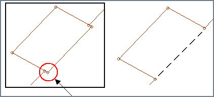
Step 7: Merge the two free edges
In the following steps, you will switch two free edges by replacing one free edge with the other free edge.
| 1. | Click Geometry > Edit > Surface Edges > Replace. |
| 2. | Click line under moved edge: and select the line shown as B in the image. |
| 3. | Click line under retained edge: and select the line shown as A in the image. |
| 4. | Click cleanup tol = and input 1.0. |
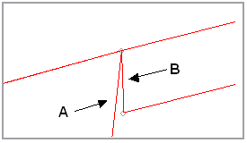
| 5. | Click replace. Notice the gap is closed and a new share edge is generated. |
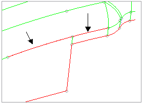
Step 8: Toggle the remaining red edges into shared edges and un-suppress two blue edges
You are still in the Edit Surface Edges panel.
| 2. | With a blue halo surrounding the edge button, click the two free edges as indicated in the image below. |
| 3. | Notice the two red free edges are now converted into shared edges. |
| 4. | Press the t key and input thetax = 145.968, thetay = -79.495 and thetaz = 30.150. |
| 5. | Click set angles to set the true view. |
Notice three blue suppressed edges are indicated in the image below. You will toggle the blue suppressed edges and turn these two suppressed edges to green shared edges.
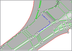
| 6. | Click return to go back to the Edit Surface Edges panel. |
| 7. | With the edge button activated, right-click the two suppressed edges to change them to green shared edges. |
Step 9: Save the cleanup result
| 1. | From the File menu, click Save As. |
| 2. | Use the file browser to save the file as Bpillar_cleanup_complete.hf. |
|