Step 1: Assigning the material and thickness to the part
| 1. | To change the material, on the tree, under Parts, right-click CRDQ Steel > Database. |
Note: You can add a user-defined material to the database by editing the material file hf.dat.
| 2. | When finished modifying the material selection, click Close. |
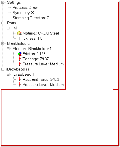
| 3. | On the tree, under Parts, select Thickness:1; on the digit 1, double-click to edit, and enter 1.5. |
Step 2: Setting symmetry conditions
On the tree, under Settings, right-click Symmetry:No, and select + X.
Step 3: Setting the stamping direction
On the tree, under Settings, right-click Stamping Direction, and select Z.
Note: In the Autotip panel, the vector selector switch lets you assign a direction. If the stamping direction of the part is not one of the principal axes, do the following: select the option N1, N2, N3; select two nodes on the model; and click set.
Step 4: Selecting the blankholder
Blankholders can be defined as the upper and lower holding surfaces that control metal flow around a shape to be formed in a draw operation. They supply a restraining force on the material during the pressing process.
HyperForm lets you to define the blankholder force in two ways: on element or edge. The correlation between the magnitude and level of the applied forces is always available. Edge blankholder force application allows you to restrain an edge by enabling automatic selection of all nodes between two user-defined nodes along a free edge of a part.
You can define the blankholder force in two ways: tonnage force or pressure level (high, medium and low).
| Note: | The pressure level is proportional to the area of blank under the blankholder as well as thickness. A pressure level of 2MPa, 5MPa and 10MPa for a 1mm blank has been chosen as a reference for Low, Medium, and High (based on practical experience). The tonnage (metric ton unit) is equivalent to the pressure times the blankholder area normalized/scaled by the thickness (1 metric ton = 9810N). |
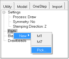
| 1. | On the OneStep tab, right-click Blankholders > New. If desired, you can double-click on Blankholder1 to change the name. |
| 2. | Right-click Blankholder1 > Elements… |
| 3. | Click elems and select on plane. |
| 4. | Select z-axis and pick a node on the binder (flat region) for B (base node). |
Nodes for Friction, Tonnage and Pressure appear below Blankholder1.
| 6. | Double-click the values for Friction and Tonnage to change the values. |
| 7. | Right-click Pressure Level, and select Medium. |
Notice that the Tonnage changes according to the selected pressure level.
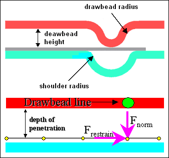
Step 5: Creating drawbeads
Modeling the exact drawbead geometry requires a large number of elements, which increases CPU time dramatically. A practical approach is to use an equivalent drawbead model by representing the drawbead analytically and providing a constant drawbead restraining force and closure force.
Use the calculate subpanel to determine the closure and restraining force based on drawbead dimensions. The restraining force is the value of the force (per unit length) applied by the bead in the plane of the blank surface. The closure force is the force (per unit length) required in the perpendicular direction to keep the drawbead closed.
| 1. | From OneStep tab, right-click Drawbeads > New > Restrain… . |
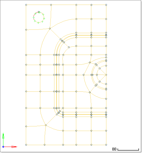
| 2. | To define the drawbeads, pick two nodes on the part as you see in the following image: |
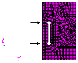
| 3. | Click Proceed, and the following message is displayed: The drawbead set has been created. |
A line representing drawbeads is created.
| 4. | Notice that Drawbead1 is created with a default Restraint Force and Pressure Level. Double-click Drawbead1 to rename it. |
| 5. | Right-click Pressure Level > Medium. Notice that Restraint Force changes based on the Pressure Level selection. |
Step 6: Tipping
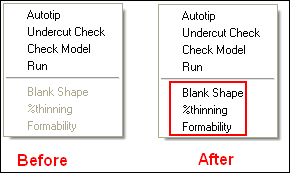
| 1. | Right-click the OneStep tab anywhere in the red box as you see below, and select Autotip. |
| 2. | In the panel, select the autotip radio button. |
| 3. | Verify the entity selector is set to comps and select the lvl1 component. |
| 4. | Verify the toggle is set to full model and keep the rest of the options as default. |
The angle to be tilted is displayed on the header bar on the left hand bottom corner and the magnitude is displayed in the angle field.
This action tilts the part by an angle calculated by HyperForm to reduce draw depth during forming.
Step 7: Checking for undercuts
| 1. | Right-click the OneStep tab anywhere in the red box as above, and select Undercut Check. |
| 2. | Click the yellow comps button to highlight it. |
| 3. | Pick the part from the screen. |
Notice the message “0 elements with undercut detected.” If undercuts are present, then the failed elements are highlighted in the model.
Step 8: Checking the model and running the analysis
| 1. | Right-click the OneStep tab anywhere in the red box as shown above, and select Check Model. |
A message is displayed on the message bar, stating “Model checked.”
| 2. | Right-click the OneStep tab, and select Run. |
| 3. | Enter a name for the run. The feasibility solver launches. |
Note: It is recommended to specify a unique directory for the analysis.
|