In this tutorial you learn how to:
| • | Create a finite element mesh |
In preparation for running the model, you specify blankholders and set constraints. After running the analysis, you view the results in a contour plot, blank shape, and FLD contour.
Exercise: Basic Draw Forming Analysis
This exercise uses the model file part1a.igs.
The imported part is considered to be clean. No free edges are present and all of the edges are stitched. However, many small surfaces are present in the part. The following steps show you how to minimize the number of these surfaces.
This tutorial uses the following panels available in the RADIOSS One Step user profile:
|
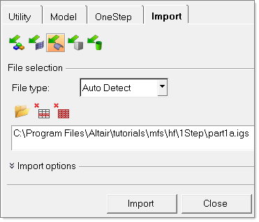
| 1. | From the File menu, select Import Geometry. |
| 2. | Click the Select Files icon  and browse to the file part1a.igs. and browse to the file part1a.igs. |
Note: The model files for this tutorial are located in the file mfs-1.zip in the subdirectory \hf\1Step\. See Accessing Model Files.
| 3. | Click Import, and then click Close. |
|
| 1. | From the File menu, click Save As. |
| 2. | Enter the file name and extension as part1a.hf. |
|
| 1. | In the Model browser, expand the Components folder. |
| 2. | For the components lvl1 and lvl7, click the colored box to select a color of your choice. |
Notice the color of the components has changed.
|
| 1. | From the toolbar, select Geometry > Edit > Surface Edges > (Un)Suppress. |
| 2. | Click lines and select all from the pop-up menu. |
| 3. | Click suppress. This suppresses all of the internal edges that are shared by the surfaces and converts the model into one big surface. |
Stay in the same panel for the next step.
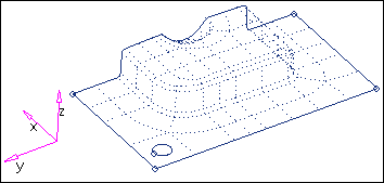
Model after lines have been suppressed
|
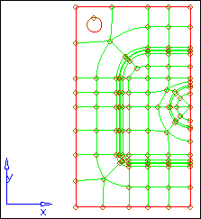
| 1. | Click lines again, and select the suppressed lines, as shown in the image below. |
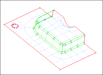
| 2. | Click unsuppress. The selected blue lines become green lines to define the corner of the fillets. (Green lines can be noticed when toggled to By Topo.) Later when you are meshing, node seeding can be generated along the green lines for better mesh quality control. |
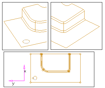
Edges to be unsuppressed prior to meshing
|
| 1. | Click Geometry > Defeature. On the left of the panel, select the pinholes radio button. |
| 2. | Click the yellow surfs button. The surfs button is outlined in cyan indicating that it is active. |
| 3. | On the model graphics, click the flat surface. |
| 4. | Click the pinholes button and select all. |
| 5. | Enter 40 in the diameter field. |
| 7. | Notice the xP display on screen indicating a pin hole has been identified with a diameter less than 40. |
|
| 2. | Click surfs >> displayed. |
| 3. | Use the settings below: |
| - | Toggle is set to interactive |
| - | Toggle is set to elems to current comp |
| - | Toggle is set to first order |
| - | Switch is set to break connectivity |
| - | Size and skew are selected |
| 5. | Click return twice to close the panel. |
|
| 1. | Click Setup > Materials and select the library subpanel. |
Notice default material types are provided under Materials in file.
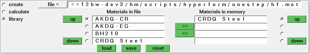
| 2. | Verify that CRDQ steel is loaded under Materials in memory. If not, click >> and load CRDQ steel under Materials in memory. |
Note: The default material for one-step solver is located at [HyperWorks installation] /hm/scripts/hyperform/hf.mat. You can edit this file and store user-defined material data into this library.
|
|
| 1. | Click Setup > Components. |
| 2. | Click Component: and enter Part. |
| 3. | Click Material: and select CRDQ Steel. |
| 4. | If you created an FLD curve, click FLD curve and select the curve. Otherwise, leave it blank, and HyperForm will automatically create an FLD curve. |
| 5. | Click thickness= and enter 1. |
| 7. | Click create to create the component. |
| 8. | Click elems and select all elements to be defined in the part component. |
|
| 1. | Switch to shaded mode by clicking on this button from the header bar:  |
| 2. | Click Setup > Constraints. |
| 3. | Click nodes and select on plane. |
| 4. | Set the direction selector to x axis. |
| 6. | Pick a point on the symmetric plane, as shown in the image below. |
| 8. | Below Constraint Type, click X. |
| 9. | Click size= and enter 10. |
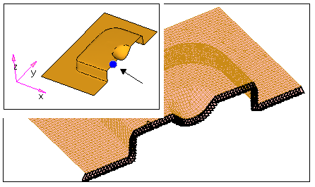
Constraints along the symmetric edge
|
Blankholders can be defined as the upper and lower holding surfaces that control metal flow around a shape to be formed in a draw operation. They supply a restraining force on the material during the pressing process.
HyperForm allows you to define the blankholder force in two ways: on element and on edge. The correlation between the magnitude and level of the applied forces is always available. Edge blankholder force application allows you to restrain an edge by enabling automatic selection of all nodes between two user-defined nodes along a free edge of a part.
You can define the blankholder force in two ways: tonnage force or pressure level (high, medium and low).
| Note: | The pressure level is proportional to the area of blank under the blankholder as well as thickness. A pressure level of 2MPa, 5MPa and 10MPa for a 1mm blank has been chosen as a reference for Low, Medium, and High (based on practical experience). The tonnage (metric ton unit) is equivalent to the pressure times the blankholder area normalized/scaled by the thickness (1 metric ton = 9810N). |
|
| 1. | Click Setup > Blankholder. |
| 2. | Click blankholder and type Blankholder 1. |
| 3. | Set the pressure level to low. |
| 4. | Click friction = and enter .125. |
| 5. | Click elems >> on plane. |
| 6. | Toggle the switch to z-axis and pick a node on the binder (flat region) for B (base node). |
| 7. | Click tolerance = and enter .3. |
Select elements on the binder region
| 9. | Click color and select a color of your choice. |
You can see the corresponding tonnage force in the tonnage= field.
|
| 2. | Enter the file name as part1a_complete.hf. |
| 3. | Click Save. This saves the file in the current working directory. The Save as… option can be used to save the file at the desired location. |
|
| 1. | Click Setup > Run Analysis. |
| 2. | Click project: and select the saved file part1a_complete. |
| 5. | Click 1- to review information about the analysis. |
| 6. | Click view output again. |
ASCII result output information is displayed.
Notice estimated press tonnage = 0.406E+02 (tons).
| 7. | Click close to close the summary. |
|
| 1. | Click load results while in the same panel. |
| 2. | Click return to exit the Run Analysis panel. |
| 3. | Press D on the keyboard and click the toggle switch to loadcols. Click on None to turn off the display of constraints. |
| 4. | In the Model browser, expand Components and click on the Geometry icon  for each component to turn off the geometry display. for each component to turn off the geometry display. |
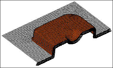
| 5. | Click Tools > %Thinning. |
| 6. | When you are finished viewing results, click return. |
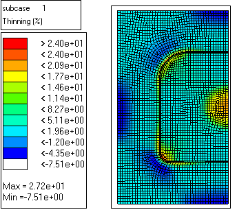
Contour plot showing % thinning
|
| 1. | Click Tools > Blank Shape. |
| 2. | Select Initial to display the minimal blank shape. |
| 3. | Select Final to view the original part geometry. |
|
| 1. | From the Utility menu, under Results, click Formability. |
| 2. | Click component, and then on the model graphics select the Blank component. |
| 4. | Pick a point on the curve that represents a corresponding element on the model, or pick an element on the model. The corresponding major (y) and minor (x) strain are displayed in the header bar. |
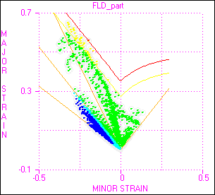
Forming Limit Diagram of part1a
|
Return to RADIOSS One Step Tutorials


