In this tutorial, you will learn how to define a bearing profile using control lines. Control lines define the bearing length at different points along the perimeter of the profile. Using this option, the initial value for the bearing lines is automatically input into the bearing profile window.
Most industrial bearing profiles have complex shapes with varying lengths and it is very difficult to match this profile with a mesh following its contours. To simplify this process, HyperXtrude allows you to specify this region using a curve called a bearing profile. For bearing profiles with varying lengths at different points, it can become tedious to select the control points and input the initial lengths.
HyperXtrude allows the control point selection to be accomplished using lines.
The bearing definition is sometimes available in the 3D CAD geometry and these can be used while creating the bearing profile. Geometric lines at locations where the bearing length changes can also be created in HyperXtrude, and these can be used as control lines to specify the bearing lines.
The model files for this tutorial are located in the file mfs-1.zip in the subdirectory \hx\MetalExtrusion\HX_0053. See Accessing Model Files.
To work on this tutorial, it is recommended that you copy this folder to your local hard drive where you store your HyperXtrude data. This will enable you to edit and modify these files without affecting the original data. In addition, it is best to keep the data on a local disk attached to the machine to improve the I/O performance of the software.
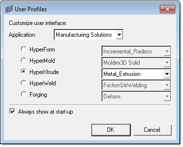
| 1. | Select Start Menu > All Programs > Altair HyperWorks > Manufacturing Solutions > HyperXtrude to launch the HyperXtrude user interface. The User Profiles dialog appears with Manufacturing Solutions as the default application. |
| 2. | Select HyperXtrude and Metal Extrusion. |
|
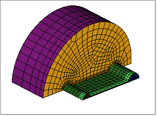
| 2. | Browse to the file HX_0053.hm and click Open. This file contains the finite element mesh for work piece, material properties, and boundary conditions. |
|
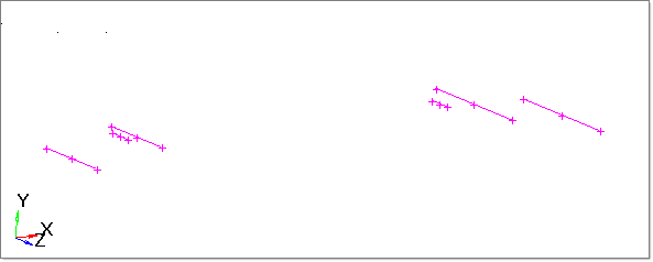
In this step, you will import the IGES file containing the bearing lines created in a CAD system.
| 2. | Select the Import Geometry icon  to change the import type to geometry. to change the import type to geometry. |
| 3. | Set the File type: field to Auto Detect. |
| 4. | Click the select file…  icon. icon. |
| 5. | Browse and select the file HX_0053a.iges. |
| 6. | Click Import to import the geometry. Notice the line data is imported into the database. |
| 7. | Click Close to close the Import tab. |
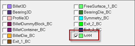
| 8. | In the Model browser, notice a component named lvl44 is created. This component contains the geometric line data. Display only this component to see the bearing lines. |
|
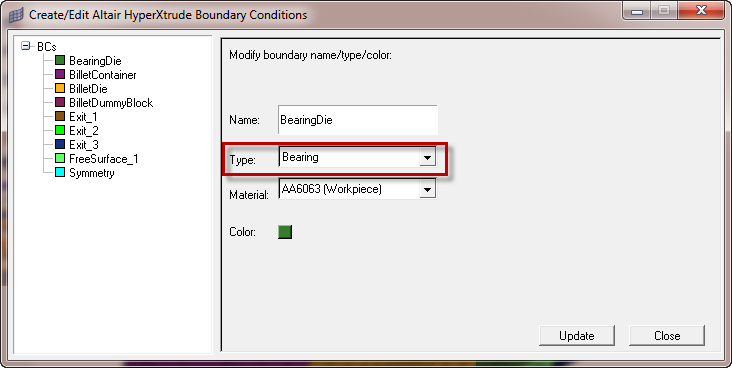
| 1. | From the Utility menu, under BCs, click Create/Edit. This displays the Create/Edit Altair HyperXtrude Boundary Conditions dialog. |
| 2. | Select BearingDie from the list of boundaries on the left hand side of the panel. |
| 3. | Right-click BearingDie and select Edit Attributes. |
| 4. | Change the boundary type to Bearing. |
| 6. | Switch to  to display the BearingSurf on screen. to display the BearingSurf on screen. |
| 7. | Click Create next to Bearing Profile: to define the bearing profile. |
| 10. | With the lines button activated, click lines and select by collector. |
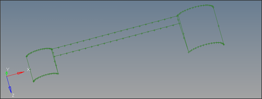
| 11. | Check lv44 and click select. |
Notice the lines are highlighted on screen.
| 13. | Under Bearing length, accept the values for Min and Max. These Min and Max values are relevant only for bearing optimization example and it is explained below. |
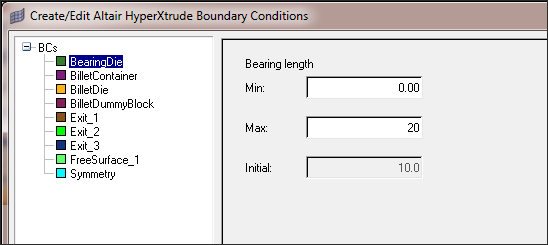
| 14. | Accept the values for Min and Max limit for bearing lines and click Next. This minimum and maximum is relevant only for bearing optimization example and it is explained below. |

This panel displays the following data for each control line:
| • | Node ID - This node ID is the closest node to bearing line. This is important to note, as even for bearing by control lines, a control node is selected internally. Hence, if you line is in between two nodes of the bearing edge, the nearest one will be selected and this will lead to an approximation. |
| • | Min – The absolute minimum length the bearing can take at this point. This value is used only for bearing optimization runs. |
| • | Max – The absolute maximum length the bearing can take at this point. This value, along with the minimum value, defines the range in which the bearing can range for bearing optimization runs. |
| • | Nominal – This is the actual bearing length at the node for the run. If you are doing an optimization study, then this will be the value used for the nominal run. |
| • | DV Tag – This provides a mechanism to tie the control points that behave in a similar manner and thus establish dependency for optimization runs. This is relevant only for optimization runs using the optimizer inside HX. |
HyperMesh interpolates the bearing length at nodes in between two control points and displays bearing profile on the screen. This profile is used in the calculations.
| 16. | Click Update. Note the bearing is non-uniform. |
| 17. | Click Close to close the Create/Edit Altair HyperXtrude Boundary Conditions dialog. |
| 18. | Close the Create Edit BC window. |
| 19. | In the Model Browser, right click Component and select Show to display all the components again. |
| 20. | From the menu bar, select File and select Save As. Save the file as HX_0053_FINAL.hm. |
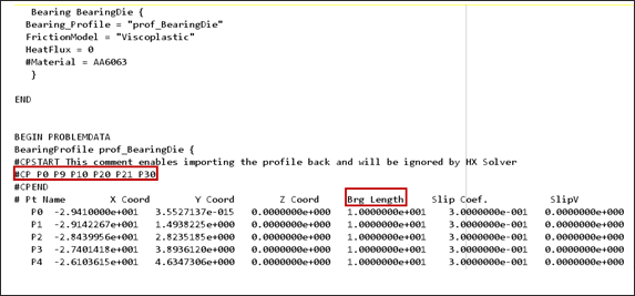
| 21. | On the Utility Menu, under Export Data, click Export/Launch Solver to export the HyperXtrude data files. Choose the correct location to save, choose the Project file name as HX_0052_FINAL and click Export. This will create .grf and .hx files. You can verify the bearing length at the bearing control points in the .grf file. Open the .grf file in a text editor and search for the keyword BearingDie and verify the bearing length at control points. |
|
Return to Metal Extrusion Tutorials


