The surface of the die that comes into contact with the extruded profile is known as bearing region. This region is used to control the material flow in an extrusion setup. By adjusting the length of this region, an extrusion engineer attempts to balance the flow exiting the die. In HyperXtrude, Bearing boundary condition is used to define this region. It is possible to define the bearing using SolidWall or SolidFluidInterface and make sure the finite element mesh matches contours of the bearing profile. Most industrial bearing profiles have complex shapes with varying lengths, and it will be very difficult to match this profile with a mesh following its contours.
To simplify this process, HyperXtrude allows you to specify this region using a curve called bearing profile. The region between this curve and the die face (along the extrusion axis) is identified as the bearing region. This approach allows you to have flexibility in meshing and therefore not requiring the mesh to conform the contours of the bearing region.
Bearing BC is made of the following components:
| • | Boundary faces that form the bearing region - this need not be exact but must be large enough to include the bearing profile. This is typically the boundary faces of the Bearing3D region in a mesh. |
| • | Bearing BC data, such as, friction type and value. |
| • | Bearing profile, which is a curve defining the actual bearing region. |
In this tutorial, you will learn how to define a bearing using control points.
The model files for this tutorial are located in the file mfs-1.zip in the subdirectory \hx\MetalExtrusion\HX_0052. See Accessing Model Files.
To work on this tutorial, it is recommended that you copy this folder to your local hard drive where you store your HyperXtrude data, for example, “C:\Users\HyperXtrude\” on a Windows machine. This will enable you to edit and modify these files without affecting the original data. In addition, it is best to keep the data on a local disk attached to the machine to improve the I/O performance of the software.
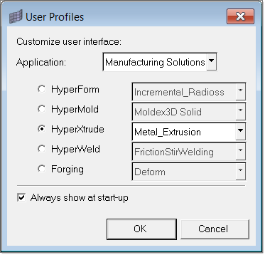
| 1. | Select Start Menu > All Programs > Altair HyperWorks > Manufacturing Solutions > HyperXtrude to launch the HyperXtrude user interface. The User Profiles dialog appears with Manufacturing Solutions as the default application. |
| 2. | Select HyperXtrude and Metal Extrusion. |
|
| 1. | From the toolbar, click the Open *.hm file icon  . . |
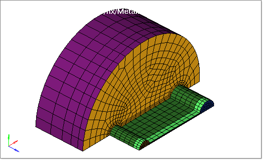
| 2. | Browse to the file HX_0052.hm. This file contains the finite element mesh for work piece, material properties, and boundary conditions. |
| 3. | Inspect the model data. |
|
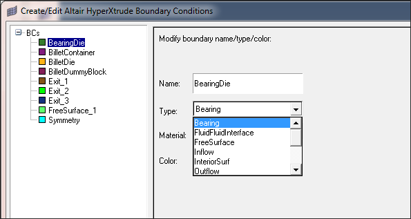
| 1. | On the Utility menu, under Boundary Conditions, click Create/Edit BC. The Create/Edit Altair HyperXtrude Boundary Conditions dialog displays. |
| 2. | Select BearingDie from the list of boundaries on the left hand side panel. |
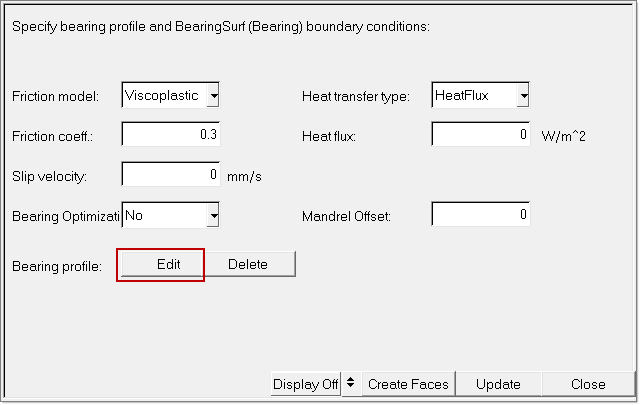
| 3. | Right-click BearingDie and select Edit Attributes. This allows you to modify the boundary condition. |
| 4. | Change the boundary type to Bearing. |
| 6. | Next to the Bearing Profile label, click Create to define the bearing profile. In the following panel, you will have to make choices about your profile and how you are going to create it. |
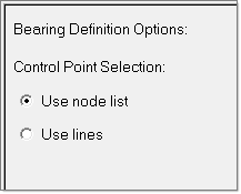
There are two methods to create bearing profile lines:
| • | Use node list: Nodes are requested to be selected for reference locations of each bearing lines. Then, minimum length (default 0.0), maximum length and initial length are specified for each individual bearing location. Initial length is applied afterwards. Bearing length is linearly interpolated (along the contour of the profile) between two defined bearing lines. |
| • | Use lines: Bearing lines are a more convenient way of designing a bearing profile. Often die manufacturers supply this information either as bearing lines or as bearing curve. If they supply a bearing curve, HyperXtrude has tools to automatically create bearing control lines from the 3D curve. If you have this data, you can define bearing profile by using the Use lines option. More details will be discussed later in the next tutorial |
| 7. | Select Use node list and click Next. |
| 8. | Click nodes >> by id. A dialog box appears. |
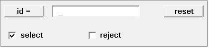
| 9. | Input node numbers in model (28587, 28578, 28557, 28547, 28620, 28628) and click ENTER. The bearing length changes at these control points. |
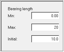
| 11. | In the next panel, you will see minimum, maximum, and the initial values to be set for all bearing lines. This is used the populate the table in the subsequent panel. You will be able edit each entry for every bearing line in the next panel. The maximum here is based on actual available length of the bearing region. Accept the default values and click Next. |
| 12. | This macro interpolates the bearing length at nodes in between two control points and displays bearing profile on the screen. This profile is used in the calculations. In this example, we will first create a uniform bearing length and then edit to make it non-uniform. This is essentially done by providing the appropriate value for nominal length. |
Click update.
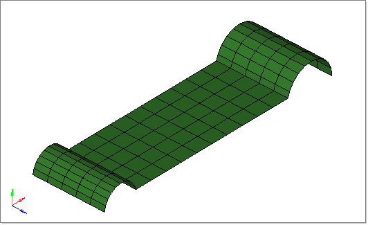
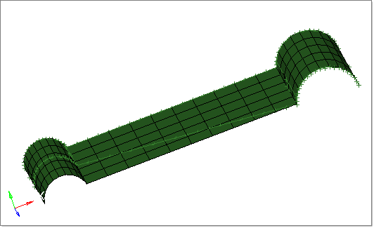
| 13. | In the Model browser, turn off the display for all the components except BearingDie_BC. The created bearing profile will be displayed. |
The following image shows the created bearing profile.
| 14. | Within Create/Edit Altair HyperXtrude Boundary Conditions, switch between Display On and Display Off  to review the bearing line with Bearing BC. to review the bearing line with Bearing BC. |
| 15. | Within Create/Edit Altair HyperXtrude Boundary Conditions, click Update. This will implement the new modification of BC. |
|
Bearing length is the measurement of the bearing surface in depth at any given location along the extrusion direction. It varies significantly in a complex extrusion, especially where section thickness differs. It is an important characteristic of extrusion dies and the key element to control the metal flow through the die. The longer the bearing length is, the larger the resistance to the flow of aluminum will be. This is mainly due to the friction introduced by the bearing. Ideally, all parts of the profile must emerge from the die at the same speed. A well-designed die will slow the profile through the thinner parts with shorter bearings in order to match the speed of the profile through the longer bearings.
In this step, you will adjust the existing bearing profile by changing the bearing length.
| 1. | In the Create/Edit Altair HyperXtrude Boundary Conditions dialog, select BearingDie from the list of boundaries on the left hand side panel. |
| 2. | Next to Bearing profile:, click Edit. |
| 3. | Under Bearing Definition Options:, verify that ONLY Edit control points is checked. |
| 5. | Under Bearing length, keep all default setting and click Next. |
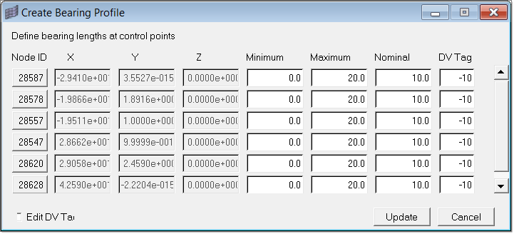
| 6. | Within the Create Bearing Profile dialog, change the Nominal values from 10.0 to 20.0 for node IDs 28547, 28620 and 28628. |
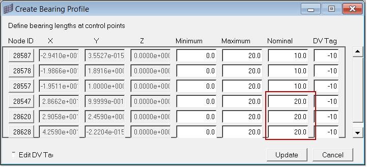
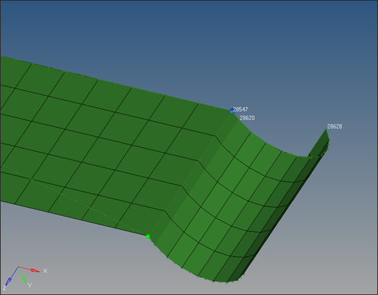
| 8. | Notice the changes in bearing length at nodes 28547, 28620, 28628 and change in the bearing profile. |
| 9. | In the Create/Edit Altair HyperXtrude Boundary Conditions dialog, click Update. This will implement the new modification of BC. |
| 10. | Click Close to complete the setup and close the Create/Edit Altair HyperXtrude Boundary Conditions dialog. |
|
| 1. | In the Model browser, turn on the display for all the components. |
| 2. | Click File > Save As and save the file as HX_0052_FINAL.hm. |
| 3. | Under the Export Data header in the Utility menu, click Export/Launch Solver and enter the project file name as HX_0052_FINAL. |
| 4. | Set the Export entities: field to All and click Export. This exports both .hx and .grf files. |
| 5. | Use any text editor to open the .grf file. |
| 6. | Search by keyword Bearing BearingDie. |
The following is the exported block which defines the bearing surface. You can verify the bearing lengths set at the control points in the image below.
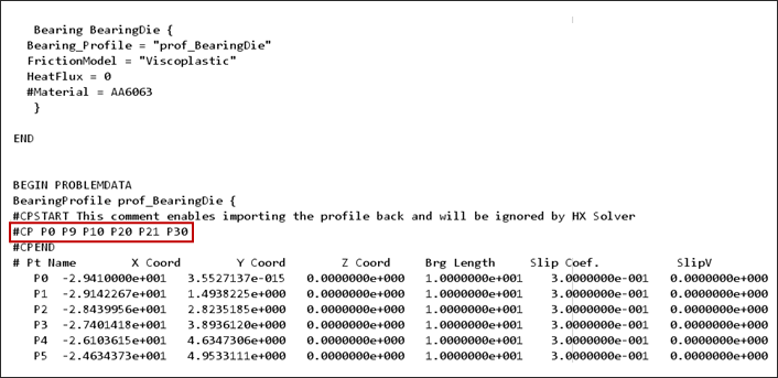
Note:
| • | Friction models are implemented in HyperXtrude to simulate resistance to sliding that occurs along the interface between two surfaces. In this tutorial, viscoplastic friction is applied. |
| • | Friction coefficient is written for each node under Slip Coef. field within the .grf file. |
| • | Friction coefficient is an empirical measurement. This value has to be measured experimentally and cannot be found through calculations. Rougher surfaces tend to have higher values. In HyperXtrude, default value is set to 0.43. |
|
This completes this tutorial. This model is ready to be solved, you can export it and solve. You can play with this model by adjusting the bearing profile (using edit option) and see how it affects the results. In fact, in the bearing optimization tutorial, you will use this feature to optimize the die design automatically by adjusting the bearing profile.
|
Return to Metal Extrusion Tutorials


