In this tutorial you will learn how to create Bearing control lines automatically from a 3D Bearing curve, which is drawn on the Bearing solid. The 3D Bearing curve defines the shape of the Bearing profile. This tutorial also explains the automatic creation using the Extrusion Wizard.
The model files for this tutorial are located in the file mfs-1.zip in the subdirectory \hx\MetalExtrusion\HX_0054. See Accessing Model Files.
To work on this tutorial, it is recommended that you copy this folder to your local hard drive where you store your HyperXtrude data. You can accomplish this in one of the ways presented in tutorial HX-0004 – preferably by adding the model to your project area. This will enable you to edit and modify these files without affecting the original data. In addition, it is best to keep the data on a local disk attached to the machine to improve the I/O performance of the software.
Bearing region in a metal extrusion die is used to control the material flow in an extrusion setup. By adjusting this region, an extrusion engineer attempts to balance the flow exiting the die.
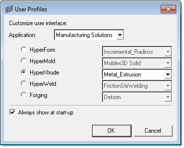
| 1. | Select Start Menu > All Programs > Altair HyperWorks > Manufacturing Solutions > HyperXtrude to launch the HyperXtrude user interface. The User Profiles dialog appears with Manufacturing Solutions as the default application. |
| 2. | Select HyperXtrude and Metal Extrusion. |
|
| 1. | From the File menu, select Open.... |
| 2. | Browse to the file HX_0054.hm and click Open. |
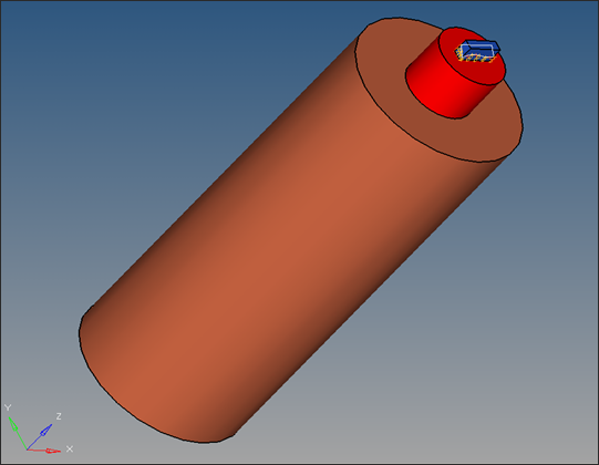
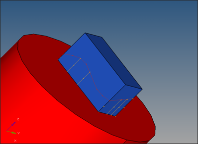
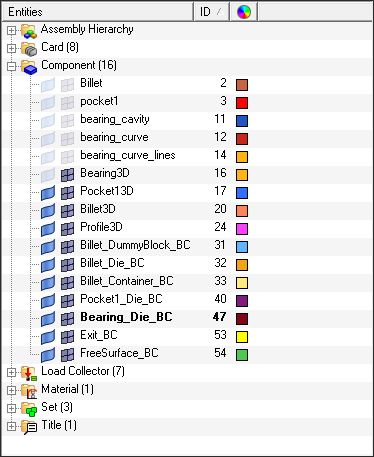
This model is solid geometry which consists of the Billet, Pocket, Bearing and Bearing-curve components.
|
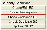
| 1. | On the Utility menu, under BCs, click on Create Bearing lines. |
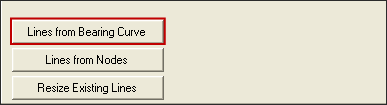
| 2. | The Bearing Utilities tab opens. Click Lines from Bearing Curve. |
| 3. | Click the yellow comps button and select the Bearing_curve component. Click proceed. |
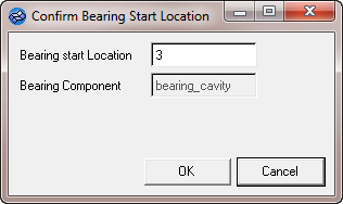
| 4. | The Confirm Bearing Start Location dialog appears. Keep the Bearing start Location set at 3 and click OK. |
The bearing curve is automatically captured and the bearing control lines are created. All the bearing control lines will be stored in the Bearing_curve_lines collector. You can check this by displaying only the Bearing_curve_lines collector in the Model Browser.
|
| 1. | On the Utility Menu, click Extrusion Wizard. Depending on how you loaded the model, the Project Browser may prompt you for action (see HX-0004 for details). |
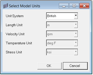
| 2. | In the Extrusion Wizard, click Set Model Units. |
| 3. | Set the Unit System field to British and click OK to close the Select Model Units dialog. |
| 4. | Click on Set Analysis Requirements. The default data on the Process Data dialog can be accepted as it is. Click Next to proceed. |
| 5. | The default data on the Analysis Data dialog can also be accepted as it is. Click Next to proceed. |
| 6. | In the Select Extrusion Components dialog, check Pocket1 under the Workpiece Components list. |
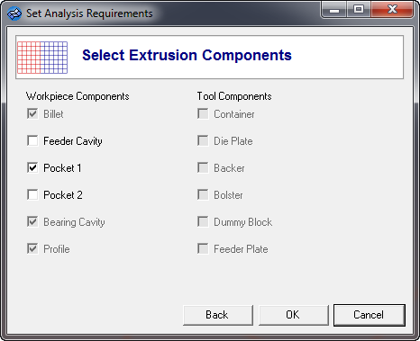
| 7. | Click OK to save and close the dialog. |
| 8. | Click on the Select Material Data checkbox. |
| 9. | In the System materials frame, expand Workpiece and select a material. Click Add to move the selected material to the Selected materials frame. |
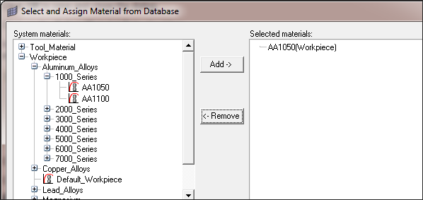
| 10. | Click Close. Closing the dialog assigns the selected material to all the 3D components created. |
| 11. | Click the Generate Workpiece Mesh checkbox. The Generate Mesh dialog opens. |
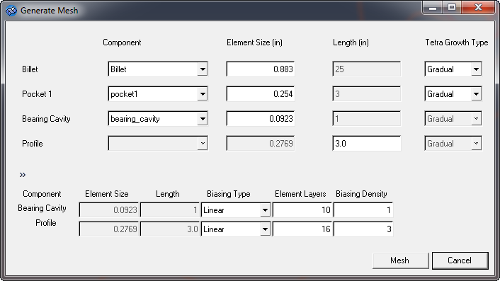
| • | Tet Growth Type – Preferred option is Gradual. Standard will produce very coarse mesh and interpolate will produce a fine mesh. It is important to have good mesh even in Billet3D component and hence, gradual is recommended. Interpolate option will produce a tetmesh with the core element size more or less of the same magnitude as the surface mesh size. For complex profiles, using interpolate may be required in welding chamber or pocket regions. |
| • | Bearing cavity and profile meshes are created by drag option. This results in PENTA6 (6-noded triangular prism) elements. For most models, size of the mesh depends a lot on the mesh in this region. In order to carefully control this, there are options to change the number of dragged layers, biasing type and density. You will find a detailed help on these options in the element biasing page of HyperMesh User’s guide. |
| • | Since the bearing cavity region has a bearing profile, it requires a near uniform and fine mesh along the extrusion axis to resolve the profile accurately. For this reason biasing is set to a low value in this region. On the other hand, profile elements can be longer near the exit region; hence, biasing is set to a larger value. Key is to inspect the mesh after it is created and change these values to create a reasonable mesh |
| 12. | Accept the default element sizes and click Mesh. |
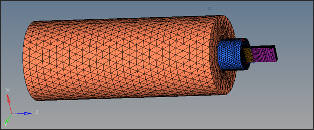
| 13. | Click OK to close the Generate Mesh dialog. |
| 14. | Click the Generate Workpiece BCs checkbox to set the process conditions. |
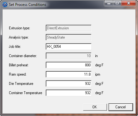
| 15. | Accept the default process conditions and click OK. This step creates the BC faces and associated loadcards for all the 3D collectors. Verify this by observing Components and Load Collector in the Model Browser. |
| 16. | Click the Create Bearing checkbox. This step automatically picks the bearing control lines component named bearing_curve_lines. |
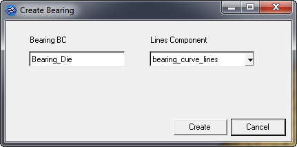
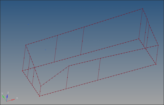
| 17. | Click Create. The bearing is automatically created. To view the bearing, isolate the display of the Bearing_Die_BC component. |
| 18. | To set the data up for a run, click on the Parameters tab on the Utility Menu to display the Define Altair HyperXtrude Analysis Parameters dialog. |
| 19. | Set the footer data in the User Commands tab to the settings displayed in the image below. This will help you invoke the solver in both interactive and batch mode. |
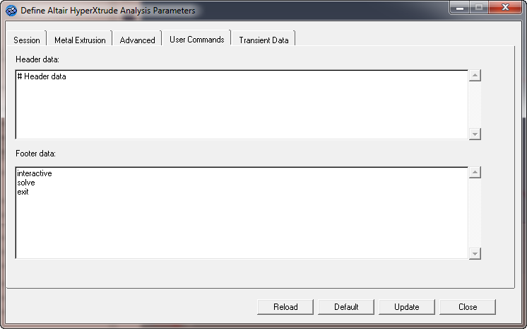
| 20. | Click Update and click Close to close the dialog. |
| 21. | From the menu bar, select File and select Save As. Save the file as HX_0054_FINAL.hm |
| 22. | Click on the Save and Export the Model checkbox in the Extrusion Wizard. |
| 23. | Export the model with the following settings: |
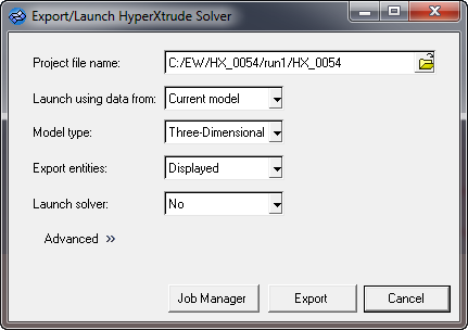
| 24. | Click on Export to generate HX_0054_FINAL.grf, and HX_0054_FINAL.hx files. |
| 25. | If you want to launch the solver interactively set the Launch solver option to Interactive and then export. |
Alternatively, you can set Launch solver to No and submit the job on e-compute.
|
Return to Metal Extrusion Tutorials


