In this tutorial, you will learn how to:
| 1. | Import a 3D CAD file with die geometry. |
| 2. | Create shared surfaces between adjacent solids. |
| 3. | Start the Extrusion Wizard and create HyperXtrude input files. |
| 4. | Launch a HyperXtrude run. |
To work on this tutorial, it is recommended that you copy this folder to your local hard drive where you store your HyperXtrude data; please refer to the tutorial HX-0004 for more details on how you can accomplish this with project browser. This will enable you to edit and modify these files without affecting the original data. In addition, it is best to keep the data on a local disk attached to the machine to improve the I/O performance of the software.
The model files for this tutorial are located in the file mfs-1.zip in the subdirectory \hx\MetalExtrusion\HX_0100. See Accessing Model Files.
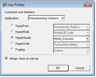
| 1. | Select Start Menu > All Programs > Altair HyperWorks > Manufacturing Solutions > HyperXtrude to launch the HyperXtrude user interface. The User Profiles dialog appears with Manufacturing Solutions as the default application. |
| 2. | Select HyperXtrude and Metal Extrusion. |
|
| 1. | Access the Import tab in one of the following ways: |
| • | Click the icon  . . |
This opens the Import tab.
| 2. | Click the Geometry icon  to set the Import File Type to geometry. to set the Import File Type to geometry. |
| 3. | Set the File Type field to Auto Detect and click the Select Files icon  . . |
| 4. | Select the file: HX_0100.stp |
| 5. | Click Import to read the die geometry. |
| 6. | Click Close to close the Import tab. |
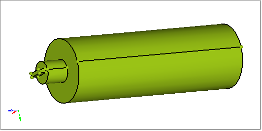
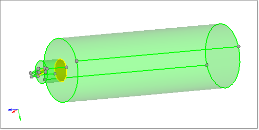
The CAD file contains three solid entities that represent the billet, pocket, and bearing region. The three solids are not connected to each other.
|
| 1. | On the menu bar, click Geometry > Edit > Solids > Boolean. |
| 2. | Under operation type:, select simple (combine all). |
| 3. | For operation, select {A-B,B} (cut A with B). |
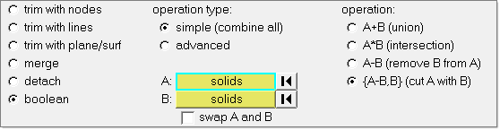
| 4. | With the A: Solids button activated, graphically select the Billet portion of the solid. |
| 5. | Activate the B Solids button and graphically select the Pocket solid and click Calculate. This will join the two solids. Once the solids are joined, the shared surface will be highlighted in yellow. |
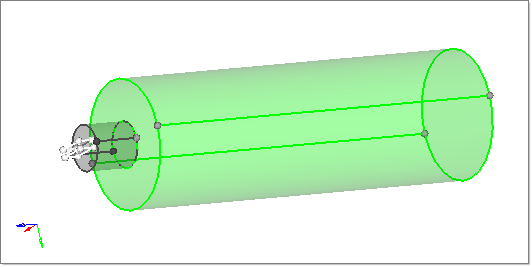
| 6. | Repeat step 4 for the remaining two solids Pocket1 and Bearing. |
Once the solids are joined, the shared surface will be highlighted in yellow.
| 7. | Click return to close the panel. |
| 8. | Click File > Save and save the file. |
|
| 1. | In the Model browser, right-click in the white space area and select Create > Component. |
| 2. | In the Name field, enter Billet, choose a color and click Create. |
| 3. | Repeat steps 1 and 2 to create two new components called Pocket1 and Bearing. |
| 4. | In the main menu, click organize to open the Organize panel. |
| 5. | Click the switch on the entity selector button to change the type to solids. |
| 6. | With the solids button active, click the Billet solid in the graphics area. |
| 7. | Change the dest component = field to Billet and click move. |
| 8. | Repeat steps 6 and 7 for the Pocket1 and Bearing solids, moving them to their respective components. |
| 9. | When finished, click return to close the Organize panel. |
| 10. | Click File > Save to save the model. |
| 11. | Now all the solids are organized into their respective components. You can check this by displaying one component at a time in the Model browser. |
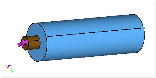
|
In this step you will use the Extrusion Wizard to prepare HyperXtrude input files.
| 1. | Click the letter “O” to open the Option panel. |
| 2. | Click the geometry subpanel and set the cleanup tol = field to 0.001. |
| 3. | Select the mesh subpanel. Change element size = 0.1 and node tol = 0.001. |
Note: It is necessary to set the node tolerance lower than the element size before using the Extrusion Wizard.
| 4. | Click return to go back to the main menu. |
|
| 1. | On the Utility menu, click Extrusion Wizard. Depending on how you loaded the model, the Project Browser may prompt you for additional action (see HX-0004 for details). |
| 2. | Click the Set Model Units checkbox. |
Notes:
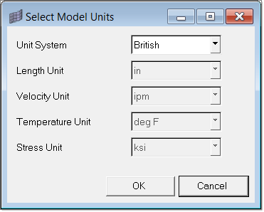
| • | Measure dimensions of the model (ex: diameter of the billet) by pressing F4 button on the key board. Find the distance between any two nodes lying diagonally opposite to each other on the circumference of the billet. The numerical value of this distance (the diameter of the billet) gives us an idea about the unit system in which the model is created. |
| • | In the present model, the billet diameter is about 8.44. Hence, it is reasonable to conclude that the length unit of the present model is ‘inches’. (8.44 mm diameter billets are practically not used in extrusion). However, you should always get the information about the model geometry units from the source that provided you the data. |
|
| 3. | Set the Unit System to British and click OK close the dialog. |
|
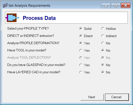
| 1. | Select Set Analysis Requirements. The Process Data window opens. |
| 2. | Observe all the default options and click Next to accept them. |
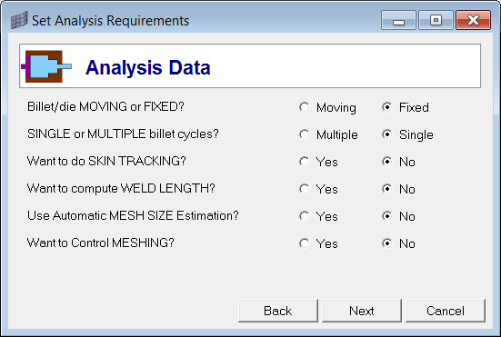
| 3. | In the Analysis Data dialog, observe the default options and click Next to accept them. |
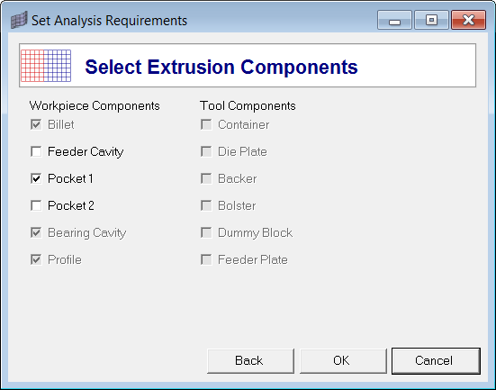
| 4. | When finished verifying all parameters, click Next to go to the Select Extrusion Components window. |
| 5. | Notice Billet, Bearing Cavity and Profile are recognized and pre-selected. |
| 5. | Check the Pocket1 component and click OK to complete the setup. |
Note: The Press Selection phase is skipped for this tutorial.
|
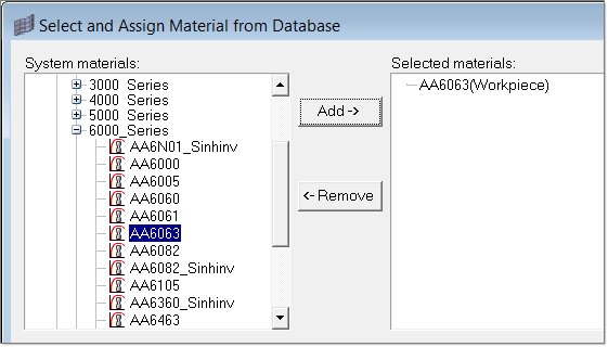
| 1. | Click Select Material Data. |
| 2. | Expand Workpiece, then expand Aluminum_Alloys and expand 6000_Series. |
| 3. | Select AA6063 and click Add to add the material under Selected Materials. |
When using the Extrusion Wizard, you do not need to assign material to the components. The selected material will be assigned to the Workpiece components automatically.
| 4. | Click Close to close the window. Inside the wizard, materials are not explicitly assigned. That step is automatically done whenever a 3D elements component collector or a 2D BC face elements collector is created. |
|
| 1. | In the Extrusion Wizard, click Generate Workpiece Mesh. The Extrusion Wizard detects the model with default settings as shown below. |
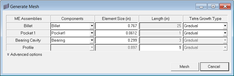
| • | Tetra Growth Type – Preferred option is Gradual. Standard will produce very coarse mesh and interpolate will produce a fine mesh. It is important to have good mesh even in Billet3D component and hence, gradual is recommended. Interpolate option will produce a tetmesh with the core element size more or less of the same magnitude as the surface mesh size. For complex profiles, using interpolate may be required in welding chamber or pocket regions. |
| • | Bearing cavity and profile meshes are created by the drag option. This results in PENTA6 (6-noded triangular prism) elements. For most models, size of the mesh depends a lot on the mesh in this region. In order to carefully control this, there are options to change the number of dragged layers, biasing type and density. You will find a detailed help on these options in element biasing page of HyperMesh User’s guide. |
| • | Since the bearing cavity region has a bearing profile, it requires a near uniform and fine mesh along the extrusion axis to resolve the profile accurately. For this reason biasing is set to a low value in this region. On the other hand, profile elements can be longer near the exit region; hence, biasing is set to a larger value. Key is to inspect the mesh after it is created and change these values to create a reasonable mesh. |
| 2. | Click Mesh. The 3D mesh is automatically created. |
Note: If you receive a message, "Error while meshing surface for bearing, please change element size", click OK to continue.
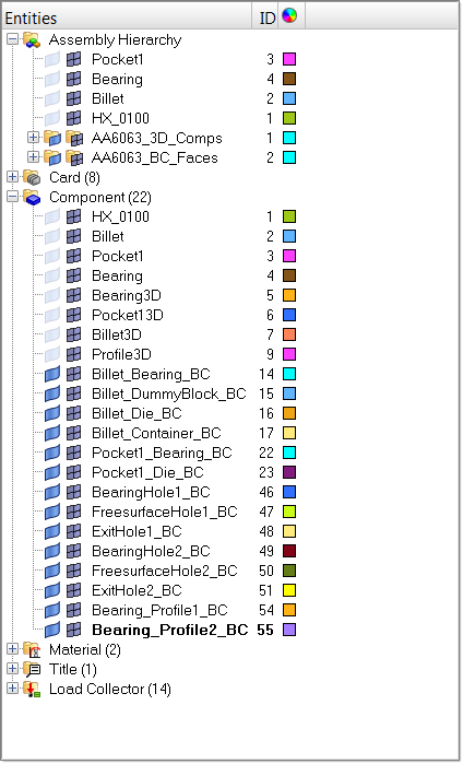
| 4. | In the Model browser, verify that 3D components Billet3D, Pocket13D, Bearing3D and Profile3D are now created. Notice that solid mesh is organized into different components accordingly. |
| 5. | Zoom in and rotate the model to review the mesh quality. |
|
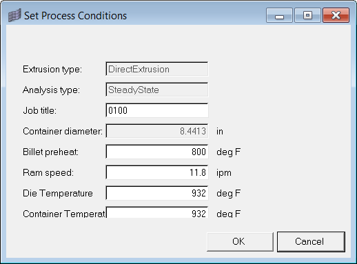
| 1. | Click Generate Workpiece BCs. This opens the Set Process Conditions dialog. |
| 2. | Verify the default input parameters and set them (if necessary) as shown below. |
| 4. | Click on the Model Browser tab and notice that related Boundary Condition components are created. |
| 5. | Click on the Extrusion Wizard tab to go back to the Extrusion Wizard. |
| 6. | Click Summary to review all the data related to Process Conditions, Material, BCs and Element Statistics. |
| • | Under the Material tab, verify that the material is assigned to all the components. |
| • | Under the BCs tab, verify the type of boundary conditions applied to the model. |
| • | Under Element Statistics tab, click on Show Element Quality to verify the quality of the generated mesh. |
| 7. | Click Close to close the dialog. |
|
| 1. | Click File > Save As… and save the file as HX_0100_FINAL.hm. |
| 2. | In the Extrusion Wizard, click Save and Export the Model. |
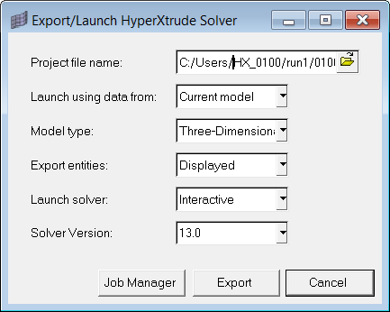
| 3. | Click Export to generate HX_0100_FINAL.grf and HX_0100_FINAL.hx files. |
The *.hx and *.grf files can be passed to the HyperXtrude solver for solving analysis.
|
In this step, you will setup environmental variables, and learn how to launch the HyperXtrude solver outside the HyperMesh GUI on PC platform.
| 1. | Set up the following two environmental variables: |
Variable name: ALTAIR_LICENSE_PATH
Variable value: C:\Altair\hw\security\altair_lic.dat
If you are pointing to a server, then value is 6200@<server-address>
| 2. | To run the HyperXtrude job using the command prompt on PC/ Unix machines in the background, ensure that the necessary data files (Jobname.grf and Jobname.hx) are present in the directory. In addition, Jobname.hx file must have the solve command at end of the file. If not, then you will have to add following lines in Jobname.tcl file): |
# User Commands
#============
solve
exit
#============
Use following command on On PC:
[Installation path]\Altair\hw\hwsolvers\bin\WIN32\hx.bat [job name]
HyperXtrude solver should be invoked via the BAT file and not directly via the EXE file.
|
| 1. | Launch the solver. Once the analysis is completed, run HyperView to post-process the results. |
|
Return to Metal Extrusion Tutorials


