This tutorial contains:
| • | Elements of the graphical user interface (GUI) features of HyperView |
| • | Page and window controls |
HyperView provides an interactive and easy-to-use environment for the visualization of engineering and result data obtained from finite element analysis (FEA). Deformed, linear static, transient and modal analysis animations can be visualized.
Exercise
In this exercise, you will:
| • | Work with a session file |
| • | Develop an understanding of the GUI |
| • | Use the page and window controls |
The model files for this tutorial are located in the file mfs-1.zip in the subdirectory \hx\MetalExtrusion. See Accessing Model Files.
To work on this tutorial, it is recommended that you copy this folder to your local hard drive where you store your HyperXtrude data, for example, “C:\Users\HyperXtrude\” on a Windows machine. This will enable you to edit and modify these files without affecting the original data. In addition, it is best to keep the data on a local disk attached to the machine to improve the I/O performance of the software.
|
The main elements of the HyperWorks Desktop graphic interface are shown in the image below:
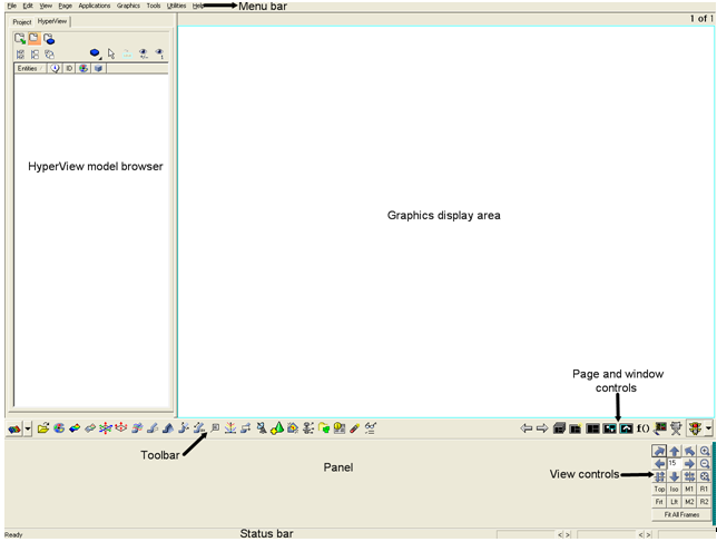
Menu Bar
|
Windows-style pull down menus that allow you to access the HyperView functions and tools are located along the top of the screen.
|
Graphics Display Area
|
Models, plots, and animations are displayed in this area. It can be divided into multiple windows.
|
Toolbar
|
Panels containing tools associated with HyperView can be accessed using the toolbar buttons. Panels are also accessible from the menu bar.
|
Panel
|
Most operations are performed using the panel options.
|
|
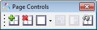
The following page controls are displayed for all applications and are used to manage pages, change page layouts, and manipulate individual windows.
Button
|
Function
|
Behavior
|
 / / 
|
Previous page / Next page
|
Displays the preceding or subsequent page.
|
 / / 
|
Add page / Delete page
|
Adds a page to the end of the current session page and makes it the active page.
Deletes the current page and makes the next page the active page.
|

|
Window layout
|
Sets the current page window layout to the icon selected from the drop down menu.
|
 / / 
|
Expand/Reduce Windows
|
Expands the active window to full screen, or reduces the expanded window to normal page layout. When one is selected, the other icon immediately becomes the only available option.
|

|
Left Only
|
Displays the Pick Target dialog, and swaps the current window with selected option.
|
 / / 
|
Window Synchronization
|
Displays the Select Windows to Synchronize dialog. Choose the windows to sync, and then select the Stop Windows Synchronization icon.
|
|
| 1. | In the toolbar, click on the Load Model icon  . A panel is drawn. . A panel is drawn. |
| 2. | Browse for the file HX_0500_000.h3d and specify it for both the Load model and Load results field. |
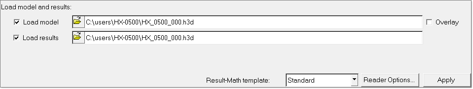
| 3. | Click Apply to load the results file into HyperView. |
|
| 1. | Click the Page Window Layout icon in the toolbar and select the three-window layout icon  . The border of the left-most window in the three window layout is cyan to indicate it is the active window. . The border of the left-most window in the three window layout is cyan to indicate it is the active window. |
|
| 1. | Make window 2 active by clicking on it. |
| 2. | Repeat step 1, clicking on window 3 this time. |
|
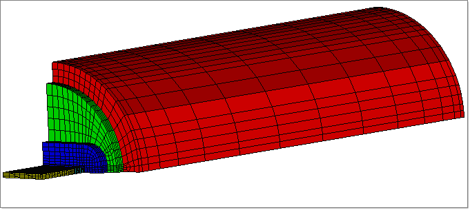
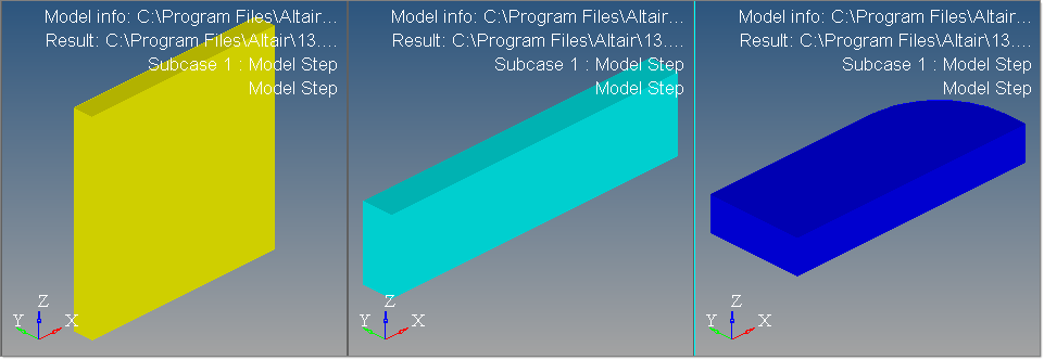
In this step you will:
| • | Display the Profile3D component in window 1 |
| • | Display the Bearing3D component in window 2 |
| • | Display the Recess3D component in window 3 |
| 2. | In the Results browser, right-click on Components and select Hide. This will switch off the display of all the components in the model. |
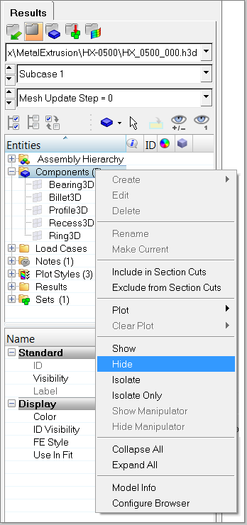
| 3. | Click on the  icon next to Profile3D to switch on the display for only Profile3D. icon next to Profile3D to switch on the display for only Profile3D. |
| 4. | Repeat the above steps for window 2 and window 3 for the components Bearing3D and Recess3D. Press F on the keyboard to fit the model in the active window. |
|
| 1. | From the File menu, select Save AS > Session. |
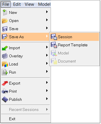
| 2. | Specify the name as HX_0500 for the MVW file and click Save. |
|
| 1. | In HyperView, from the File menu, select Open > Session. |
| 3. | Notice the contents of the session. It contains the number of pages and window layouts created in the previous session. |
|
Return to Metal Extrusion Tutorials


