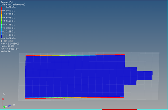
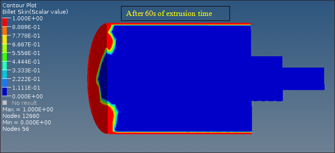
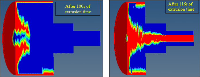
Billet skin tracking is used to determine when the material in the billet skin area enters the product. Thus, you can detect when the impurities in the skin start to flow into the product and hence, determine the butt length.
In this tutorial you will learn how to:
| • | Automatically set up a Skin Tracking model as transient moving model using the Extrusion Wizard |
| • | Perform transient analysis |
| • | Demonstrate the use of the SetVariableTimeStep command from the Parameters dialog |
The model files for this tutorial are located in the file mfs-1.zip in the subdirectory \hx\MetalExtrusion\HX_0303. See Accessing Model Files.
To work on this tutorial, it is recommended that you copy this folder to your local hard drive where you store your HyperXtrude data, for example, “C:\Users\HyperXtrude\” on a Windows machine. This will enable you to edit and modify these files without affecting the original data. In addition, it is best to keep the data on a local disk attached to the machine to improve the I/O performance of the software.
Altair HyperXtrude can perform transient analysis of metal extrusion. It has two modes to perform these analyses: TransientFixedBoundary and TransientMovingBoundary. In this tutorial, you will use the TransientMovingBoundary option. In TransientFixedBoundary analysis, time-dependent behavior of the extrusion process is studied without actually moving the components of the model such as dummy block, etc. On the other hand, in TransientMovingBoundary analysis, movement of the dummy block and billet are simulated in the analysis.
Prerequisites for Skin Tracking Model:
| • | Billet component should have separate solid components for a) Billet (core), and b) Billet Skin |
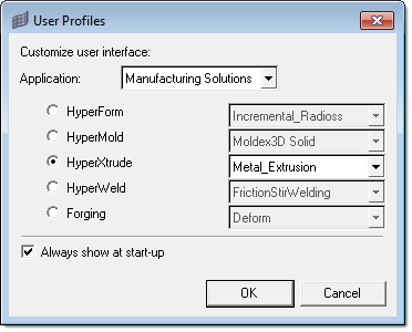
| 1. | Select Start Menu > All Programs > Altair HyperWorks > Manufacturing Solutions > HyperXtrude to launch the HyperXtrude user interface. The User Profiles dialog appears with Manufacturing Solutions as the default application. |
| 2. | Select HyperXtrude and Metal Extrusion. |
|
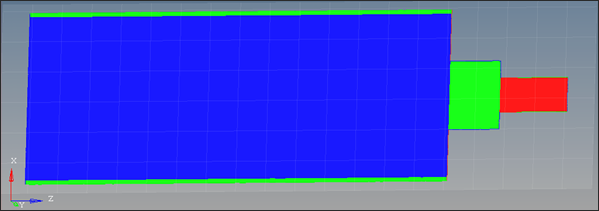
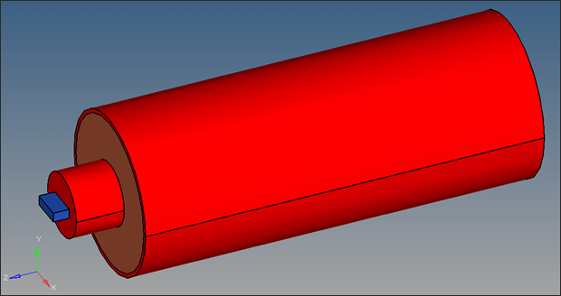
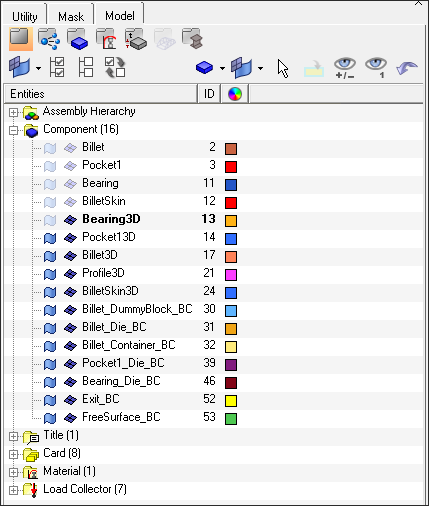
| 1. | Load the model HX_0303.hm. This model has four components: Billet, BilletSkin, Pocket1, and Bearing. There are shared surfaces between the connected components. |
|
| 1. | On the Utility menu, click Extrusion Wizard. Depending on how you loaded the model, the Project Browser may prompt you for additional action (see HX-0004 for details). |
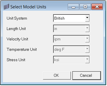
| 2. | In the Extrusion Wizard, click Set Model Units. |
Note: Measure dimensions of the model by pressing the F4 button on the key board to get an idea about the units of the model.
The length unit of the current model is inches (Billet diameter is measured about 9.5).
| 3. | Set the Unit System field to British and click OK. |
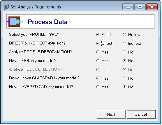
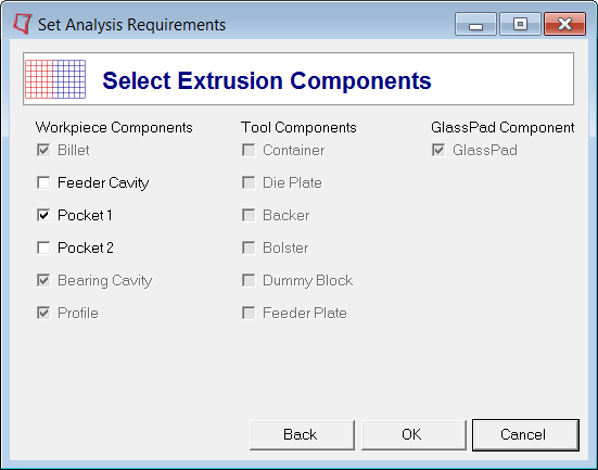
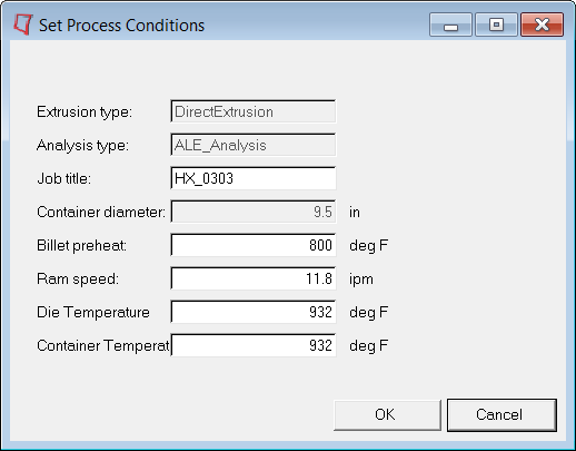
| 4. | Click Set Analysis Requirements and set the Process Data as shown in the image below. |
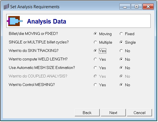
| 6. | In the Analysis Data page, select Yes for the question "Want to do SKIN TRACKING?" |
This will automatically select Moving for the question "Billet/die MOVING or FIXED?"
| 8. | In the Select Extrusion Components page, notice that Billet, Bearing Cavity and Profile components are already selected. Select Pocket 1 and click OK to save the data and close window. |
You will skip the Select Press Data option as the model does not have that information.
|
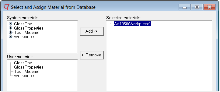
| 1. | Click Select Material Data. |
| 2. | Expand Workpiece, then expand Aluminum_Alloys and expand 1000_Series. |
| 3. | Select AA1050 and click Add to add the material under Selected Materials. You do not need to assign a material in the Extrusion Wizard. The selected material will be assigned to the workpiece automatically. |
| 4. | Click Close to close the Select and Assign Material from Database window. |
|
| 1. | Click the Generate Workpiece Mesh option. |
| 2. | Input the size of the elements as shown below. |
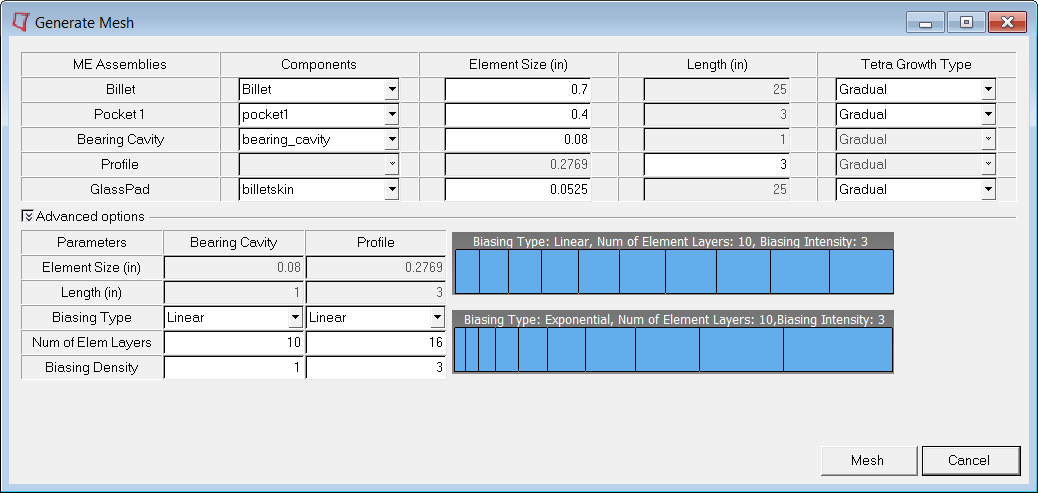
| 3. | Click Mesh. This will generate 3D mesh for Billet, Billetskin, Pocket 1, Bearing and Profile in the component collectors Billet3D, BilletSkin3D, Pocket13D, Bearing3D and Profile3D respectively. |
| 4. | After the mesh is created, click OK and close the window. |

|
| 1. | Click Generate Workpiece BCs and accept the default parameters. |
| 2. | Click OK. This creates BC faces and associated load cards for all the 3D collectors. |
|
| 1. | On the Utility menu, under Process Data, click Parameters. The Define Altair HyperXtrude Analysis Parameters dialog displays. |
| 3. | Click on the Variable Time Step pull down menu and select on. |
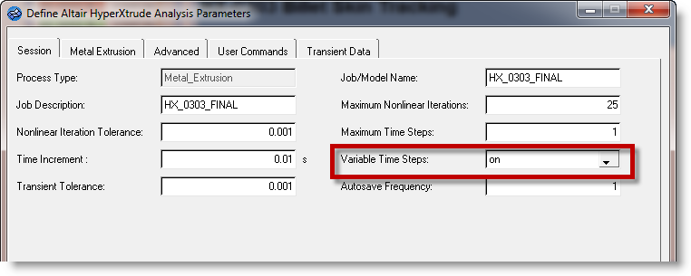
| 4. | Click on Update. This will enable the Variable Time Step panel in the Transient Data tab. |
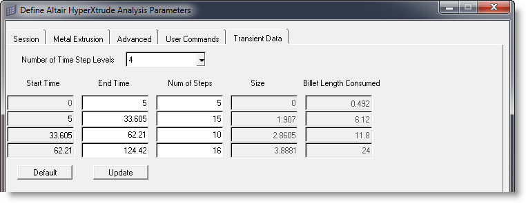
| 5. | Click on the Transient Data tab. |
| 6. | Click on the Number of Time Step Levels pull down menu and set it to 4. |
| 7. | Accept the default values for End Time and Number of Steps. |
| 9. | Click on the User Commands tab. Include solve and exit commands in the Footer data. |
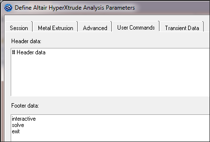
| 10. | Click on Update to save the commands and click on Close to exit the dialog. |
|
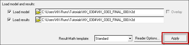
| 1. | In the Extrusion Wizard, click on Save and Export the Model. |
| 2. | Export the model with the following: |
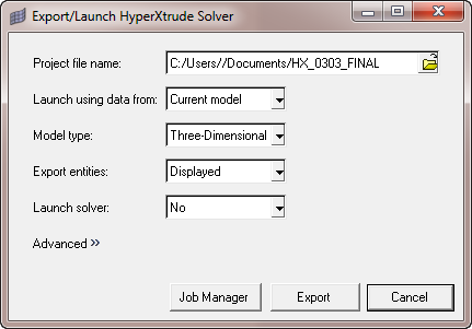
| 3. | Click on Export to generate HX_0303_FINAL.grf and HX_0303_FINAL.hx files. |
| 4. | To launch the solver interactively, set the Launch Solver option to Interactive, and then export. |
This writes the data files and launches the solver in batch. You can then post-process the results using the file HX_0302_FINAL_000.h3d in HyperView.
|
Return to Metal Extrusion Tutorials