In this tutorial, you will perform a time-dependent analysis to track interface between two billets. Aluminum extrusion is a cyclical process and each cycle starts with a new billet. This method is often referred to as billet-on-billet extrusion.
There are two common procedures used for billet-on-billet extrusion. In the first one, the remainder of the old billet in the container is sheared off. This sheared off region is determined by the butt length. Then the new billet is added. This billet welds with the material of the old billet in the pockets and feeder plate. In the second procedure, the discard is not removed and the new billet welds the portion remaining in the container. In both procedures, there will be a zone in the extruded part that has a mixture of old and new billet. Depending on the application, the quality of the material in this zone may not be acceptable due to a variety of reasons. Interface tracking analysis helps to identify this zone. It should be noted that you can do interface tracking only in a transient analysis.
In general, transient analysis is used:
| • | to perform skin tracking analysis. |
| • | to perform billet interface tracking analysis. |
| • | to determine the cyclic heat transfer state of the tool material (when used with multiple cycles). |
| • | to determine how the material flow may change during extrusion as the billet shrinks. However, to correct a die, it is recommended that you first run a steady state analysis for verification |
This tutorial describes billet interface tracking analysis to perform the scrap (weld length) computation.
During this exercise, you will learn how to use Extrusion Wizard to quickly set up a transient analysis problem for weld length computation. Final results will also be analyzed using HyperView.
The model files for this tutorial are located in the file mfs-1.zip in the subdirectory \hx\MetalExtrusion\HX_0304. See Accessing Model Files.
To work on this tutorial, it is recommended that you copy this folder to your local hard drive where you store your HyperXtrude data, for example, “C:\Users\HyperXtrude\” on a Windows machine. This will enable you to edit and modify these files without affecting the original data. In addition, it is best to keep the data on a local disk attached to the machine to improve the I/O performance of the software.
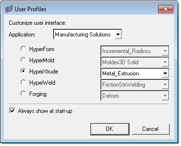
| 1. | Select Start Menu > All Programs > Altair HyperWorks > Manufacturing Solutions > HyperXtrude to launch the HyperXtrude user interface. The User Profiles dialog appears with Manufacturing Solutions as the default application. |
| 2. | Select HyperXtrude and Metal Extrusion. |
|
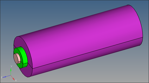
| 1. | Load the file HX_0304.hm. This file has three components: Billet, Pocket1 and Bearing. |
| 2. | Inspect the model data using the interface GUI and macros. Review the geometry by displaying the topology as described below. |
| • | From the toolbar, click  By Topo to review topology of the model. By Topo to review topology of the model. |
| • | From the toolbar, click Shaded Geometry and Surface Edges  . . |
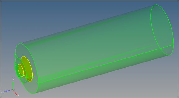
| Note: | The geometry data needs to be carefully examined to ensure no defects exist within the model. You are encouraged to complete HyperMesh tutorials HM-2000 ~ HM-2070 to have a complete understanding of how to create, review, and repair geometry data. |
| This model is clean and also contains shared surfaces between the connected components Billet-Pocket1 and Pocket1-Bearing. (Notice the yellow areas indicating shared faces between two solids). In HyperMesh, you are allowed to keep the same 2D face mesh pattern between multiple solids when shared faces exit. |
The model is now ready for setting up the analysis parameters.
In the following steps, you will use the Extrusion Wizard to setup the analysis parameters and process conditions.
|
| 1. | On the Utility menu, click Extrusion Wizard. Depending on how you have loaded the model, the Project Browser may prompt you for additional action (see HX-0004 for details). |
| 2. | In the Extrusion Wizard, select the Set Model Units checkbox. |
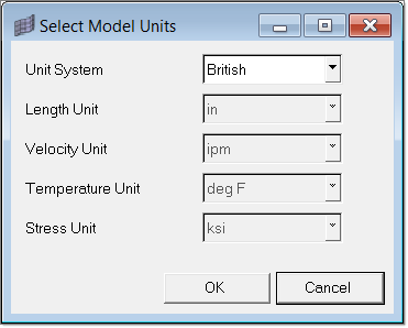
| Note: | Measure dimensions of the model (ex: diameter of the billet) by pressing F4 button on the key board. Find the distance between any two nodes lying diagonally opposite to each other on the circumference of the billet. The numerical value of this distance (the diameter of the billet) gives us an idea about the unit system in which the model is created. |
| In the current model, the billet diameter is about 8. Hence, it is reasonable to conclude that the length unit of the present model is ‘inches’ (8 mm diameter billets are not usually used in extrusion practice). |
| 3. | Set the Unit System to British and set the options as shown in the figure below. Click OK. |
|
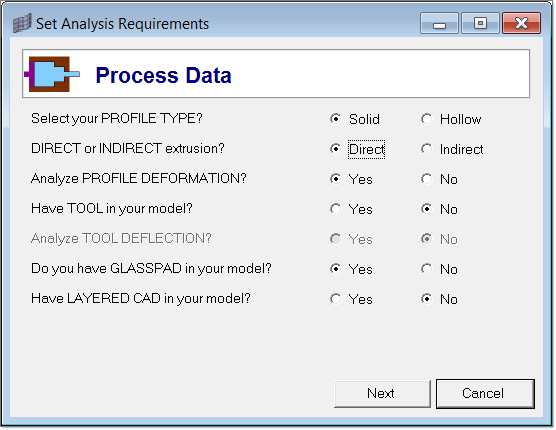
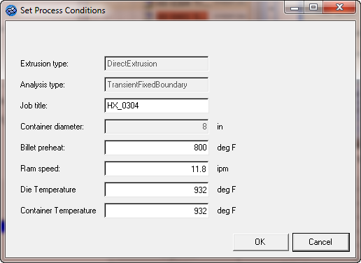
| 1. | Select Set Analysis Requirements. The Process Data dialog opens. |
| 2. | Set the Process Data as shown below and click Next. |
| 3. | In the Analysis Data page, select ‘Moving’ to the question, “Billet/die MOVING or FIXED?” |
Select ‘Yes’ to the question, “Want to compute WELD LENGTH?”
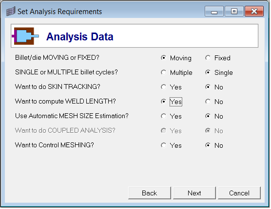
| 4. | Click Next to select the extrusion components. Notice that the Extrusion Wizard already selected the components Billet, Bearing Cavity and Profile. |
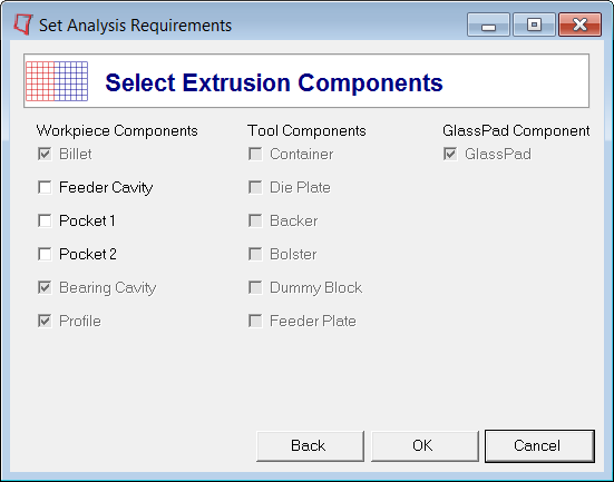
| 5. | Select Pocket1 and click OK. |
You will skip the Select Press Data option as the model does not have that info.
|
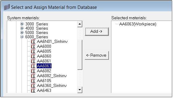
| 1. | Click the Select Material Data checkbox. |
| 2. | Expand Workpiece, then expand Aluminum_Alloys and expand 6000_Series. |
| 3. | Select AA6063 and click Add to add the material under Selected materials. |
You do not need to assign a material to the components in the Extrusion Wizard. The selected material will be assigned to the workpiece components automatically.
| 4. | Click Close to close the Select and Assign Material from Database window. |
|
| 1. | Click Generate Workpiece Mesh. The Generate Mesh dialog opens. Notice that Extrusion Wizard already picked the components for Billet, Pocket1 and Bearing Cavity. |
Note: Always rename the components by proper names so that the Extrusion Wizard identifies the components by default.
Element sizes for these components are also calculated and displayed automatically. Modify the values (if necessary) to those as shown below.
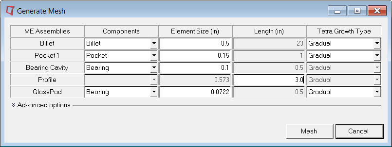
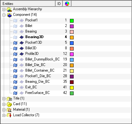
| 2. | Click Mesh, and then click OK. The 3D tetra mesh is created automatically. In the Model browser, notice that solid mesh is organized into different components: Bearing3D, Pocket13D, Billet3D and Profile3D accordingly. |
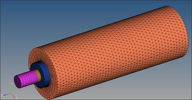
| 3. | Zoom in and rotate the model to review the mesh quality. You can check the quality of the elements by clicking on Summary > Element Statistics > Show Element Quality. |
|
| 1. | Click on the Generate Workpiece BCs checkbox. |
| 2. | Input the parameters as below: |
| 4. | Click on the Model Browser tab and notice that related Boundary Condition components are created. |
| 5. | Click the Extrusion Wizard tab to go back to the Extrusion Wizard. |
| 6. | Click the Summary button to review all the data. |
| 7. | Click Close to close the Model Summary dialog. |
|
| 1. | In the Extrusion Wizard, click Parameters. |
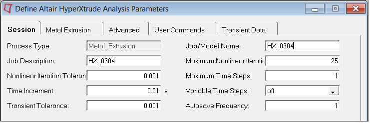
| 2. | On the Session tab, enter the information in the fields as shown below: |
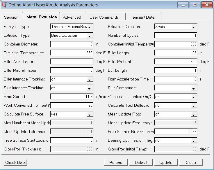
| 3. | Click the Metal Extrusion tab. |
| 4. | Verify Analysis Type is set to TransientMovingBoundary. |
| 5. | Ensure that Billet Interface Tracking field is set to on. |
| 7. | Click the User Commands tab. |
| 8. | In the Footer data field, type solve and exit. |
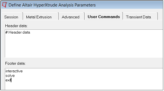
| 9. | Click Update. Click Close to close the Parameters window. |
|
| 1. | Click File > Save As… and save the file as HX_0304_FINAL.hm. |
| 2. | In the Extrusion Wizard, click the Save and Export the Model checkbox. Enter the following information: |
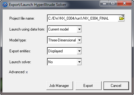
| 3. | Click on Export to generate HX_0304_FINAL.grf and HX_0304_FINAL.hx files. |
| 4. | If you want to launch the solver interactively, set the Launch Solver option to Interactive and then export. |
| 5. | Alternatively, you can set the Launch solver field to No and submit the job on e-compute. |
|
| 2. | Click the Load Model icon  and retrieve the HX_0304_000.h3d file. Make sure both Load model and Load results are checked. and retrieve the HX_0304_000.h3d file. Make sure both Load model and Load results are checked. |
| 3. | Click Apply. Notice that both the model and result files are loaded into HyperView. |
| 4. | Click Contour  . . |
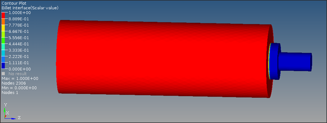
| 5. | Change Result type to Billet Interface (s), and click Apply. |
Billet Interface is a scalar value that varies between 0 and 1. Value 0 indicates old billet and Value 1 indicates new billet. When a new extrusion cycle begins, the pocket, bearing and profile regions contain old material. As extrusion progresses, the new billet material enters these regions. Eventually, the profile contains 100 percent new material. The transient weld length computation simulates this process and we can visualize this with the help of animation controls in HyperView.
The following image shows the initial state where the pocket, bearing and profile regions are full of old material.
| 6. | Click the Animation Control icon  from the toolbar menu. from the toolbar menu. |
Since this is a transient analysis (Transient Moving boundary), multiple timesteps exist.
| 7. | Click  and move to the last timestep. and move to the last timestep. |
Notice from the HyperView title that you have a total of 30 time steps with end time = 20 sec. Also, you have results for only one cycle.

| Note: | You can also simulate more than one cycle. For that you need to make changes in the .hm file. From the Utility Menu, click the Parameters button and select the Metal Extrusion tab. Change the Number of Cycles, export and solve again. |
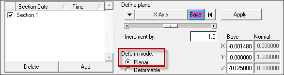
| 8. | To create a section cut plane normal to X–Axis, click the Section Cut icon  on the toolbar. on the toolbar. |
| 9. | Under the Define plane: header, select X-Axis. |
| 10. | Under Deform mode: select the Planer radio button. |
| 11. | Click Add to create a Section 1. |
| 12. | Notice Section cut view is activated on the screen. |
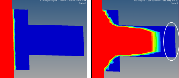
The following images show the billet interface result at various times. In the two images shown below, the profile exit region contains only the old billet material. The new billet material percentage is zero.
In the image below on the left side, the profile exit region contains a mixture of old and new billet materials whereas in the picture on the right side it contains only new billet material (100 percent).
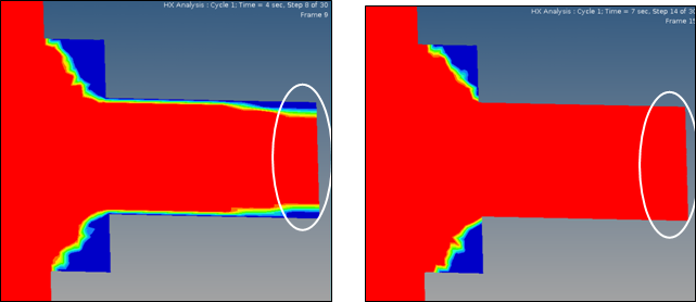
| Note: | High values (red color) indicate new billet material and low values (blue color) indicate old billet material. The intermediate values indicate the possible interface regions where a mixed of old and new billet could exist. It is engineer’s judgment to decide the threshold value. For a top quality product, you can consider keep only the red regions and discard the rest. |
|
Return to Metal Extrusion Tutorials


