In this tutorial, you learn how to create a finite element mesh from the 3D CAD file.
Outline of the Tutorial
| 1. | Load the HyperMesh file and inspect the model |
Note: The model files for this tutorial are located in the file mfs-1.zip in the subdirectory \hx\MetalExtrusion\HX_0022. See Accessing Model Files.
To work on this tutorial, it is recommended that you copy this folder to your local hard drive where you store your HyperXtrude data, for example, “C:\Users\HyperXtrude\" on a Windows machine. This will enable you to edit and modify these files without affecting the original data. In addition, it is best to keep the data on a local disk attached to the machine to improve the I/O performance of the software.
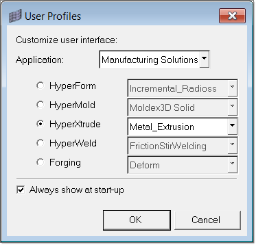
| 1. | Select Start Menu > All Programs > Altair HyperWorks > Manufacturing Solutions > HyperXtrude to launch the HyperXtrude user interface. The User Profiles dialog appears with Manufacturing Solutions as the default application. |
| 2. | Select HyperXtrude and Metal Extrusion. |
|
| 2. | Browse to the file HX_0022.hm. |
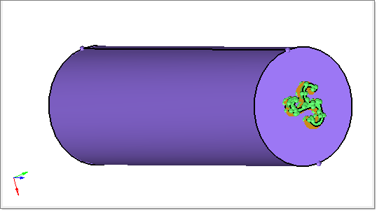
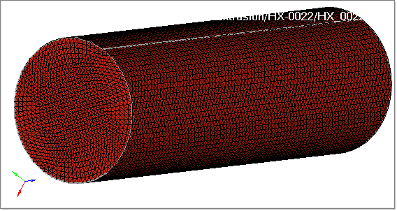
This model contains three components: Billet, Bearing, and BearingLines. The Bearing component contains a solid for the bearing region of the die. The Billet component contains the solid geometry of the billet. It should be noted that the diameter of the billet solid is equal to the container ID and not billet OD. The BearingLines component contains lines that will be used to create the bearing profile BC. When solids of two regions are in contact with each other, the common surface should be marked as shared indicating that surface is shared by both the solids. In this model, this is already established using the Solid Edit panel. This is a prerequisite for creating a connected mesh between different components of the workpiece.
|
Create components for the Billet, Bearing and Profile elements.
| 1. | Click on the Model tab to display the Model browser. |
| 2. | Right-click on Component. This opens a context sensitive menu with options to edit component properties. |
| 3. | Select Create to add a new component. The Create Component window opens. |
| 4. | Enter the component name as Billet3D and select different color. Click Create to create the component. |
| 5. | Repeat steps 2 through 4 to create the Bearing3D and Profile3D components. |
|
| 1. | In the Model browser, expand the Component folder, right-click on the Bearing component and select Isolate. |
| 2. | Select automesh from the main menu. |
| 3. | With the yellow surfs button active, select the surface shared by Billet and Bearing. |
| 4. | Enter the element size as 0.025 and toggle mesh type to trias. |
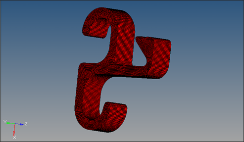
| 5. | Click mesh to create the surface mesh. This will create a mesh with at least 5 elements through the thickness of the profile. |
| 6. | Click return twice to close the panels. |
| 7. | Use the Model browser to set Bearing3D as the current component. Right-click again and select Show. |
| 8. | Select the Drag panel from the main menu. |
| 9. | Select the drag elems subpanel and toggle to Z-axis for the drag direction. |
| 10. | Click the yellow elems button and select displayed. |
| 11. | In the distance= field, enter 0.5. |
| 12. | In the on drag = field, enter the number of elements as 15. |
| 13. | Click drag+ to create 3D elements in bearing region. |
| 14. | Click return to close the panel. |
|
| 1. | On the Utility menu, select 2D Elems Only. |
| 2. | Click Mesh > Delete > Elems. Click elems >> displayed. |
| 3. | Click delete entity to delete the 2D bearing elements created during Step 4. |
| 4. | In the Model browser, right-click on the Billet component and select Isolate. |
| 5. | Right-click on Billet3D and select Make Current. Right-click again and select Show. |
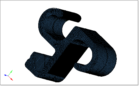
| 6. | Click Mesh > Create > Tetramesh and select the volume tetra subpanel for meshing. |
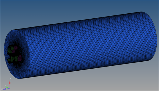
| 7. | With the solids button activated, select the Billet solid. Set the element size to 0.25 and make sure the match existing mesh check mark is ON. Click mesh to create a tetra mesh inside the Billet. |
| 8. | Click return to close the panel. |
|
| 1. | Use the Model browser to make Profile3D the current component. |
| 2. | In the Model browser, right-click on Bearing3D and select Isolate. |
| 3. | From the main menu, click on faces to open the Faces panel. |
| 4. | Toggle the switch to elems. Click elems >> displayed. |
| 5. | Click find faces. The faces found are placed into a component named ^faces, which is displayed in the Model browser. |
| 6. | In the Model browser, isolate the ^faces component, then show the Profile3D component. |
| 7. | Select the Drag panel from the main menu. |
| 8. | Select the drag elems subpanel and toggle to Z-axis for the drag direction. |
| 9. | Click on one of the elements from the unshared end of the bearing surface (surface in XY Plane). Click elems >> by faces. All the elements on this face are now selected. |
| 10. | In the distance= field, enter 0.5. |
| 11. | In the on drag = field, enter the number of elements as 15. |
| 12. | Select linear for bias style and enter 1.5 for bias intensity. |
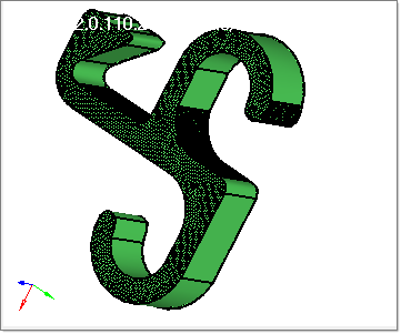
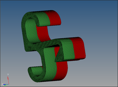
| 13. | Click drag+ to create elements in the profile region. |
| 14. | Click return to close the panel. |
| 15. | In the Model browser, right click on the ^faces component and select Delete to delete the ^faces collector. Display all the 3D components and save the model with 3D elements for billet, bearing, and profile. The same procedure can be used for solid dies with pockets and hollow dies. |
|
The Model Summary macro displays information regarding mesh size, element type, boundary conditions, and materials. Here are some guidelines for checking mesh quality.
| • | Max. Aspect ratio: TET4 < 8, PENTA6 <12, PYRAMID5 < 12; HEX8 <25 |
The way to understand the above requirements is, for example, that the recommended aspect ratio for tet4 elements is that it should be less than 8. If this criteria is met then those element are of good quality. Hence by the test “Aspect Ratio < 8”, we check if the elements aspect ratio is less than 8. If yes, then it is considered a pass, if not the element is considered a failed element. HyperXtrude solver can accept reasonably large aspect ratio for PENTA6 and HEX8 elements. Most models use PENTA6 in the Bearing3D and Profile3D region, hence, the test “Aspect Ratio < 8” is quite stringent and should be taken with this guideline in mind.
| • | Min. value for “tet collapse” for elements in portholes and weld chamber is > 0.2 |
| 1. | In the Utility menu, click Model Summary. |
| 2. | Click the Element Statistics tab. Here you can see the number of elements, nodes, element type, etc. |
| 3. | Click Show Element Quality. The quality of all the elements in the model is checked. |
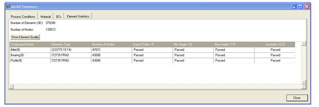
| 4. | Click Close to close the window. |
|
| 1. | From the File menu select Save As. |
| 2. | Save the file as HX_0022_FINAL.hm. |
|
Return to Metal Extrusion Tutorials


