The die geometry is sometimes stored as 2D lines. This is common for solid profiles. In such cases, the geometry creation features in HyperMesh can be used to create 3D solids of the tool and workpiece geometries. In this tutorial, you will learn how to:
| 1. | Import 2D CAD files that contains geometry in the form of lines. |
| 3. | Edit and trim surfaces, |
The model files for this tutorial are located in the file mfs-1.zip in the subdirectory \hx\MetalExtrusion\HX_0003. See Accessing Model Files.
To work on this tutorial, it is recommended that you copy this folder to your local hard drive where you store your HyperXtrude data, for example, “C:\Users\HyperXtrude\” on a Windows machine. This will enable you to edit and modify these files without affecting the original data. In addition, it is best to keep the data on a local disk attached to the machine to improve the I/O performance of the software.
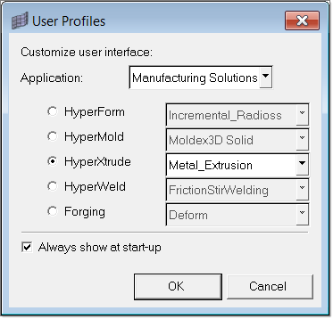
| 1. | Select Start Menu > All Programs > Altair HyperWorks > Manufacturing Solutions > HyperXtrude to launch the HyperXtrude user interface. The User Profiles dialog appears with Manufacturing Solutions as the default application. |
| 2. | Select HyperXtrude and Metal Extrusion. |
|
| 1. | Click File > Import to open the Import tab. |
| 2. | Click the Geometry icon  to set the Import File Type to geometry. to set the Import File Type to geometry. |
| 3. | Set the File Type field to Auto Detect and click the Select Files icon  . . |
| 4. | Select the file: C:\Users\HyperXtrude\HX_0003\HX_0003.igs |
| 5. | Click Import to read the die geometry. |
| 6. | Click Close to close the Import tab. |
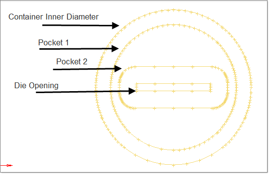
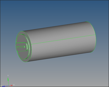
The die geometry contains lines that represent container inner diameter, two pockets and die opening.
|
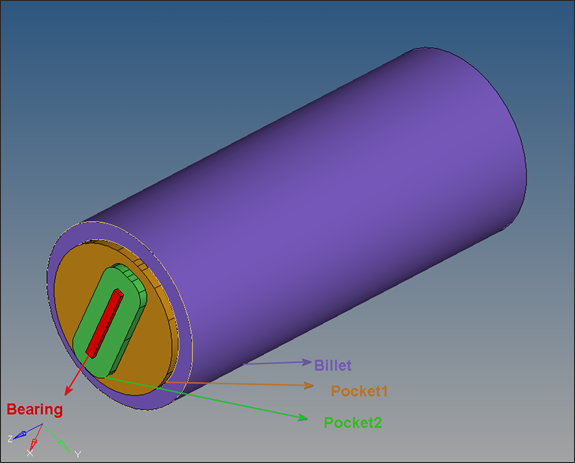
The lines are in a component called lvl2. Next you will create components to store the geometry for billet, pockets, and bearing.
| 1. | Click on the Model tab to display the Model browser. |
| 2. | Right-click on Component. This opens a context sensitive menu with options to edit component properties. |
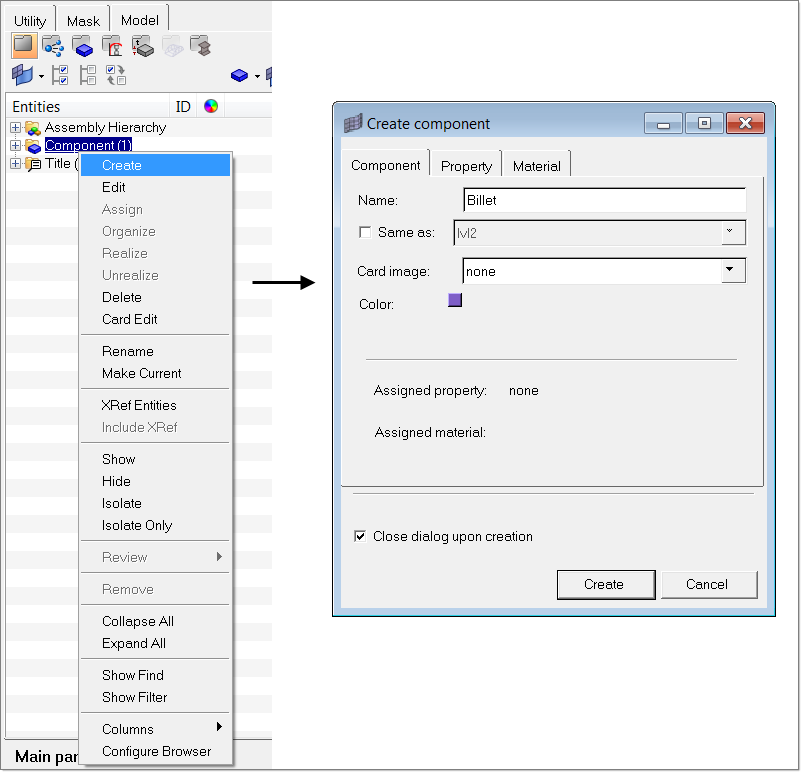
| 3. | Select Create to add a new component. The Create Component window opens. |
| 4. | Enter the component name as Billet and select different color. |
| 5. | Click Create to create the component. |
| 6. | Repeat steps 2 through 5 to create the Pocket1, Pocket2, and Bearing components. |
|
| 1. | Right-click on the Billet component in the Model browser and select Make Current. |
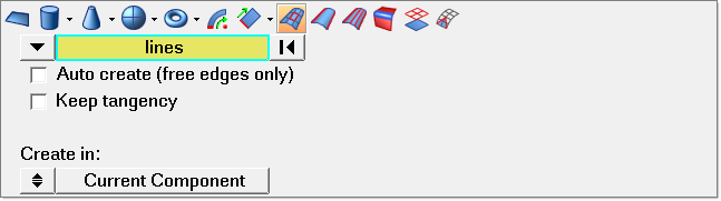
| 2. | Click Geometry > Create > Surfaces > Spline/Filler. |
| 3. | Click the switch to set the selector to lines. |
| 4. | Clear both auto create (free edges only) and keep tangency. |
| 5. | With the lines selector button active, select the lines corresponding to the container inner diameter (lines on the outer circle). |
| 6. | Make sure the Create in toggle option is set as Current Component and click create. |
| 8. | Click Geometry > Edit > Surfaces > Trim with Lines. You will use this panel to trim the surface to create an opening for the first pocket. |
| 9. | Under the with lines section, highlight the surfs button and graphically select the surface just created. |
| 10. | Click the lines button directly below the surfs button to activate it, and select the lines that represent the perimeter of the Pocket. |
| 11. | Click the toggle to set the trim direction to normal to surface. |
| 12. | Select the keep line endpoints option. |
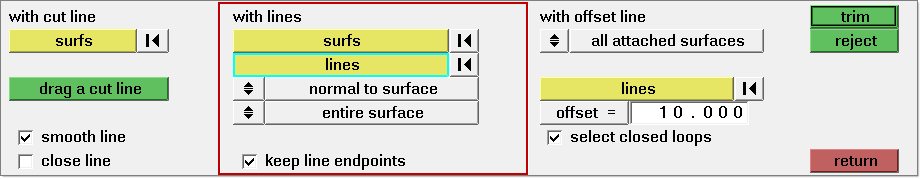
| 13. | Click trim to cut the surface. |
| 14. | Click return to close the panel. |
| 15. | From the main panel, select delete to open the Delete panel. |
| 16. | Click surfs and discard the inner surface. |
| 17. | Click return to close the panel. |
| 18. | Using the Model browser, set Pocket1 as the current component. |
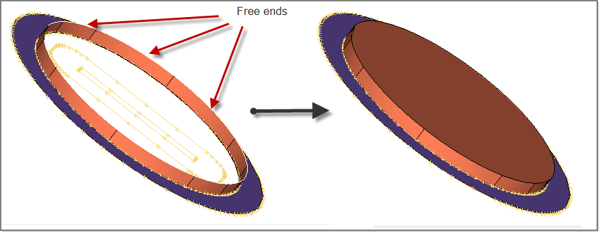
Next you will create the pocket inner walls by dragging the line segments on the pocket perimeter by 10 mm.
| 19. | Click Geometry > Create > Surfaces > Drag along Vector |
| 20. | Click the switch to lines and set the distance field to 10. |
| 21. | Set the drag direction to z-axis. |
| 22. | With the lines button active, select the line segments on the perimeter of Pocket 1 and click drag+. You can select all segments or drag each segment at a time. |
| 23. | Go the spline/filler subpanel by clicking the  icon. With the lines button active, select all free ends of these surfaces and click Create. This will create a flat surface that represents the inner walls of Pocket1. icon. With the lines button active, select all free ends of these surfaces and click Create. This will create a flat surface that represents the inner walls of Pocket1. |
| 24. | Repeat steps 8 through 23 to trim this flat surface to create an opening for the second pocket. |
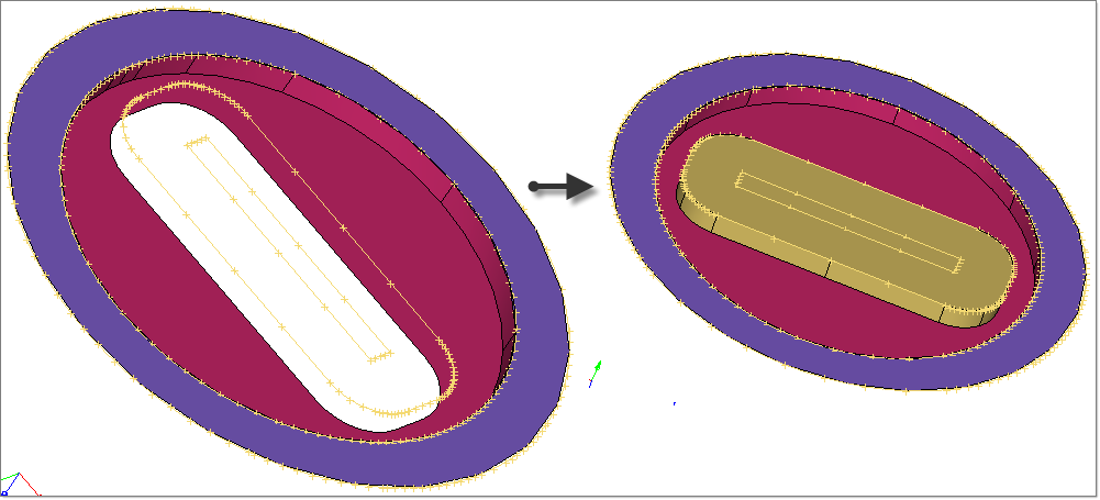
| 25. | Repeat steps 8 through 23 to create the die opening and bearing surface. Here the bearing length is set to 5 mm. |
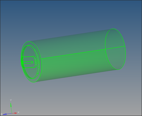
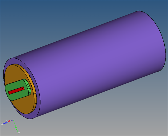
| 26. | To create the billet, select the outer most lines that represent the container wall and drag them in 500 mm in negative Z direction. |
| 27. | Close the back end with filler surface. |
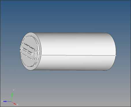
This collection of closed surfaces represents the region enclosed by container, dummy block and die face.
|
Next you will create solid volumes that represent each component.
| 1. | Make sure all surfaces are connected and they form a closed volume. If there are any open edges, go to the Edge Edit panel and connect the surfaces. |
| 2. | On the main menu, select the Solids panel and open the bounding surfs subpanel by clicking the  icon. icon. |
| 3. | Check the Auto select solid surfaces option. |
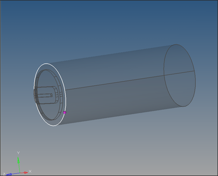
| 4. | With the surfs button active, graphically click on one surface. If all surfaces are connected and form a closed volume, all surfaces will be highlighted. |
| 5. | Click create to create one solid volume. |
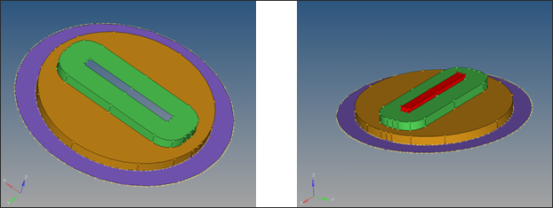
| 6. | To trim the solid to create volumes that represents each component (Billet, Pocket1, Pocket2, and Bearing), select solid edit on the main menu. |
| 7. | Select the trim with plane/surf subpanel. |
| 8. | Under the with plane: section, with the solids button active, graphically select the solid. |
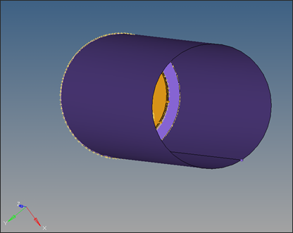
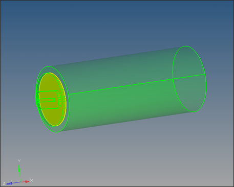
| 9. | Change the toggle to z-axis and with B button active, select a base point on the shared surface between the Billet and Pocket1. |
| 10. | Click trim to trim the solid into two parts. The shared surface between the two solid parts appears in yellow. |
| 11. | Click return to close the panel. |
| 12. | From the main menu, select organize. |
| 13. | With the solids button active, graphically select the Billet portion of the solid. Set destcomponent to Billet and click move to organize this solid part into Billet component. |
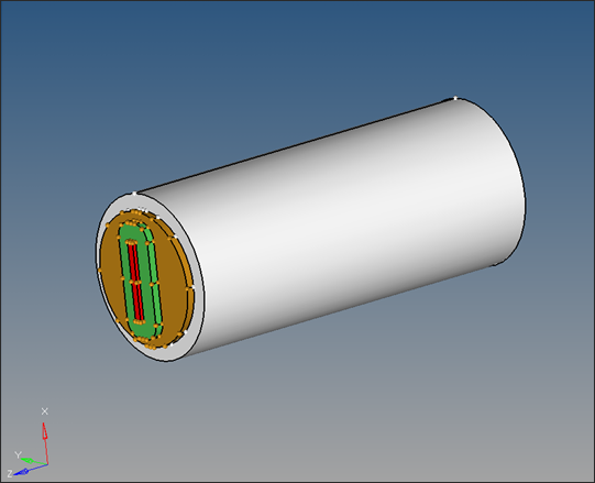
| 14. | Repeat the steps 7-11 to organize the remaining portion of the solid into proper components (i.e. Pocket1, Pocket2 and Bearing). |
| 15. | Try to display the individual solid components to make sure the solid is trimmed into proper components correctly. |
Alternatively, solid can first be trimmed into different components and all the components can be organized into respective collectors at once.
|
Once the cleanup operations are completed, save the model.
|
Return to Metal Extrusion Tutorials


