HyperMesh has several functions that require definition of a volume, such as creating tetrahedral and hexahedral meshes. This can be done either with surfaces that enclose the volume, or with solid geometry entities. Working with solids provides a couple of advantages over surfaces. Selecting the volume for the function requires only a single click because solids represent the volume with a single entity, as opposed to surfaces. Solids that are topologically connected to each other also allow the functions being used to recognize the connection. Creating mesh in these cases allows mesh in adjacent volumes to automatically have proper connectivity.
In this tutorial, you will learn:
| • | What 3D topology looks like |
Solids are geometric entities that define a three-dimensional volume. Geometric entities are defined as follows:
| • | Point: 0 dimensional; has only x, y, and z coordinates |
| • | Line: 1-dimensional; has length, can be curved through 3-dimensional space |
| • | Surface: 2-dimensional; has an area |
| • | Solid: 3-dimensional, has a volume |
Creating and Editing Solid Geometry
The model files for this tutorial are located in the file mfs-1.zip in the subdirectory \hx\MetalExtrusion\HX_0002. See Accessing Model Files.
To work on this tutorial, it is recommended that you copy this folder to your local hard drive where you store your HyperXtrude data, for example, “C:\Users\HyperXtrude\" on a Windows machine. This will enable you to edit and modify these files without affecting the original data. In addition, it is best to keep the data on a local disk attached to the machine to improve the I/O performance of the software.
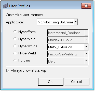
| 1. | Select Start Menu > All Programs > Altair HyperWorks > Manufacturing Solutions > HyperXtrude to launch the HyperXtrude user interface. The User Profiles dialog appears with Manufacturing Solutions as the default application. |
| 2. | Select HyperXtrude and Metal Extrusion. |
|
| 2. | Browse to the file HX_0002.hm. |
|
| 1. | Click Geometry > Create > Solids > Bounding Surfaces. |
| 2. | Verify that the Auto select solid surfaces option is checked ON. |
| 3. | Click the yellow Surfs button and select any single surface on the part. All of the surfaces should automatically be selected. |
| 4. | Click Create to create the solid. The status bar indicates that a solid has been created. The solids are identified by thicker lines than surfaces. |
| 5. | Click return to go back to the main menu. |
|
Before you proceed to this step, verify that fixed points are checked on by clicking the Display Fixed Points icon  in the Visualization toolbar. in the Visualization toolbar.
| 1. | Open the Solid Edit panel. |
| 2. | Go to the trim with plane/surf subpanel. |
| 3. | With the solids entity selector active, graphically select the solid. |
| 4. | Switch the plane selector from N1, N2, N3 to z-axis. |
| 5. | Press and hold the left mouse button, and move the mouse cursor over the edge shown below. The edge should highlight. |
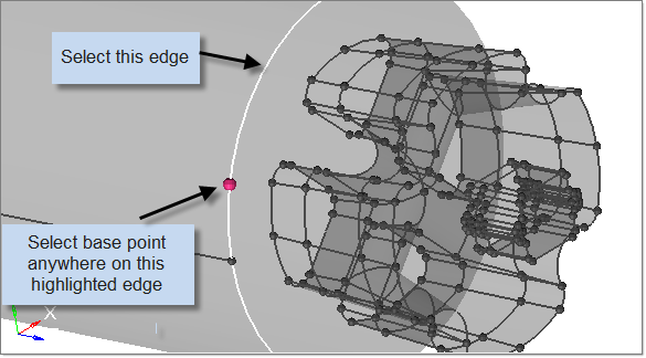
| 6. | Release the mouse button, and left-click anywhere along the highlighted edge. |
A purple temp node appears at the location to indicate the selection for the base node.
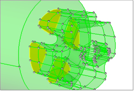
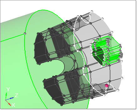
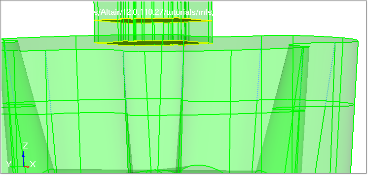
| 7. | Click Trim to trim the solid. The solid will be trimmed at the selected edge. Shared surfaces (shown in yellow color) are also created. |
| 8. | Repeat steps 3 through 7 to further trim the right part of the trimmed solid. |
| 9. | Click on the right part of the solid. Only that portion of the solid will be selected. |
| 10. | Verify that plane selector is set to z-axis. |
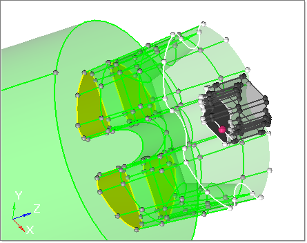
| 11. | Click on the pink button B and select the edge and a base point on the edge as shown below. Click trim. |
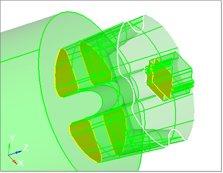
| 12. | Again trim the top portion of the solid. Select the edge and the base point as shown in the image below. |
| 13. | Click trim. The original solid is now trimmed into four solid parts. All these are connected at the shared surfaces shown in yellow color. |
| 14. | Click return to go back to the main menu. |
|
| 1. | Open the Edge Edit panel. |
| 2. | Select the (un)suppress subpanel. |
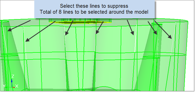
| 3. | Select lines, and select the lines as shown below. There are a total of eight lines that need to be suppressed on the weld chamber. Suppressing these lines will help to eliminate poor quality elements. |
| 4. | Set breakangle = to 30. |
| 5. | Click suppress to suppress the edges. You can see that the same edges become suppressed (turn as blue dotted lines). |
| 6. | Click return to go back to the main menu. |
|
| 1. | Click Collectors > Rename. |
| 2. | Go to the individually subpanel. |
| 3. | Verify the entity type is set to comps. |
| 4. | Click original name = and select the component lvl1, from the list of components. |
| 5. | Click once in the new name = field to highlight its text. |
| 6. | Type Billet and click rename. |
| 7. | Repeat steps 4 through 6, and rename the component lvl2 to Portholes. |
| 8. | Repeat steps 4 through 6, and rename the component lvl3 to Bearing. |
| 9. | Repeat steps 4 through 6, and rename the component lvl4 to Profile. |
|
| 1. | Click Geometry > Organize > Solids. |
| 2. | Verify the entity type is set to solids. |
| 3. | Select solids, and select the solid region in the graphics window that represents the billet portion of the geometry. |
| 4. | Click dest component = and select Billet. |
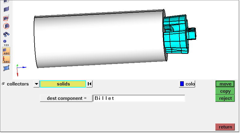
| 6. | Repeat steps 3 through 5 and organize the solid geometry as shown below. |
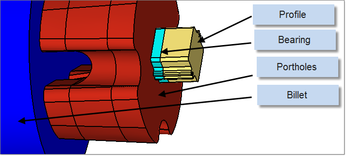
Model organization of solid entities
|
With the solid editing and organizational operations completed, save the model.
|
Return to Metal Extrusion Tutorials


