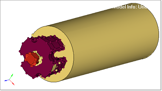
Geometry can be imported from many sources. The files can come from various programs and in different formats. Sometimes even a single format may have variations. Because of all these factors, surfaces of imported parts might not be properly connected. A number of functions rely on having surfaces properly connected, especially the Automesh panel. This section guides you through using various geometry cleanup tools to restore proper surface connectivity to part geometry.
In this tutorial, you will:
| • | Delete untrimmed surfaces |
| • | Set the cleanup tolerance |
| • | Delete duplicate surfaces |
The benefits of importing and repairing CAD are:
| • | Correct any errors in the imported geometry |
| • | Create the simplified part needed for the analysis |
| • | Ensure proper connectivity of mesh |
| • | Obtain a desirable mesh pattern and quality |
Importing and Repairing CAD Geometry Data
The model files for this tutorial are located in the file mfs-1.zip in the subdirectory \hx\MetalExtrusion\HX_0001. See Accessing Model Files.
To work on this tutorial, it is recommended that you copy this folder to your local hard drive where you store your HyperXtrude data, for example, “C:\Users\HyperXtrude\” on a Windows machine. This will enable you to edit and modify these files without affecting the original data. In addition, it is best to keep the data on a local disk attached to the machine to improve the I/O performance of the software.
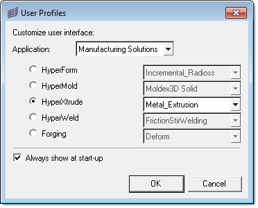
| 1. | Select Start Menu > All Programs > Altair HyperWorks > Manufacturing Solutions > HyperXtrude to launch the HyperXtrude user interface. The User Profiles dialog appears with Manufacturing Solutions as the default application. |
| 2. | Select HyperXtrude and Metal Extrusion. |
|
| 1. | Observe where the model has incorrect connectivity and missing or duplicate surfaces. |
| 2. | From the main panel, click edge edit. |
| 3. | Note that the surface edges are now colored according to their topology status. This occurs because the Geometry Color option  Auto is set to Auto. Auto is set to Auto. |
| 4. | Click the Wireframe Geometry icon  and the Shaded Geometry & Surface Edges and the Shaded Geometry & Surface Edges  icon to explore the different display modes. icon to explore the different display modes. |
| 5. | The toolbar contains icons that control the display of the surfaces and surface edges. Surfaces can be shaded with or without edges, or wireframe. Right-click the icons to access the drop down menu for additional options. Place your mouse over the cursor to view a description of the button’s functionality. |
| 6. | Set the display mode back to Wireframe Geometry . |
| 7. | Click the Visualization icon  and select the Topology icon and select the Topology icon  . . |
Visualization controls the display of the surfaces and surface edges. Surfaces can be shaded or wireframe. The check boxes within this menu turn the display of the different edge types and fixed points (surface vertices) on or off.
| 8. | Clear all the check boxes except the Free check box. |
Only the free edges should be displayed.
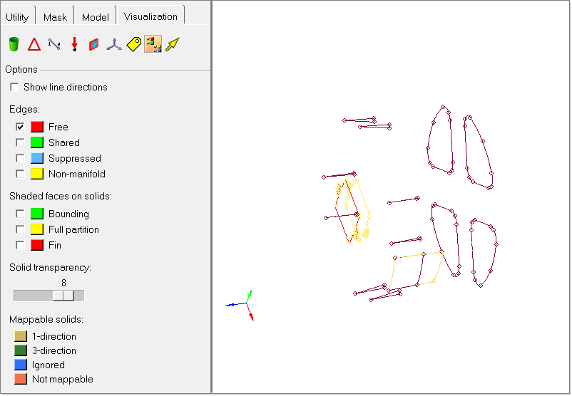
| 9. | Observe the free edges and make a mental note of where they are. The free (red) edges show where there is incorrect connectivity or gaps. |
| 10. | Note the locations where there are closed loops of free edges. These are locations that probably have missing surfaces or are not equivalenced. |
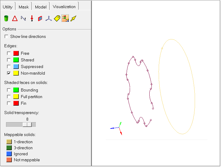
| 11. | In the Visualization tab, select only the Non-manifold edges check box. Observe the non-manifold edges and make a mental note of where they are. |
Free edges indicating surface discontinuities of the die cavity.
The non-manifold edges show where there are more than two surfaces sharing an edge, which might be incorrect connectivity. For this part, there are yellow edges surrounding two areas. This tells us there are possible duplicate surfaces in these locations.
| 12. | In the Visualization tab, select all the check boxes. |
| 13. | Click the Shaded Geometry & Surface Edges icon. The surfaces should now appear solid rather than having only their edges displayed. |
| 14. | Rotate, zoom, and pan to locate any errors in the geometry. |
| 15. | Make a mental note of the areas to be worked on. You find: |
| • | Multiple missing surfaces around weld chamber |
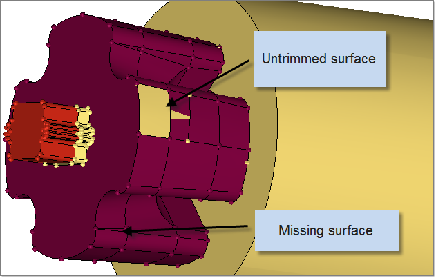
Untrimmed surface and multiple missing surfaces
| 16. | Click the Wireframe Geometry icon to change back to wireframe display. |
| 17. | Click return to close the panel. |
|
| 1. | From the main panel, click Delete. |
| 2. | Change the entity selector to surfs. |
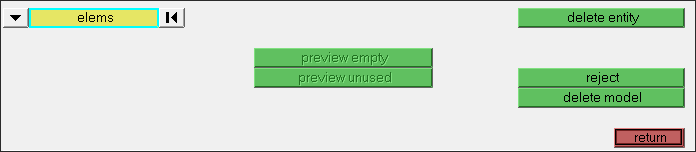
| 3. | Select the untrimmed surface shown in the previous figure. |
|
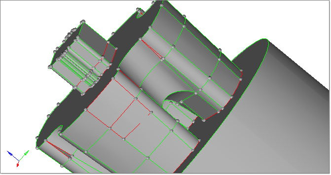
| 1. | From the toolbar, change the Geometry Color Mode to By Topo BY TOPO. |
In Topology color mode, each color represents different topological mode:
| • | Free edge (red color): The edge is owned by one surface. On a clean model, free edges appear only along the outer perimeter of the part and internal holes. Free edges that appear between two adjacent surfaces indicate the existence of a gap between the two surfaces. |
| • | Shared edge (green color): The edge is owned by two adjacent surfaces. When the edges between two adjacent surfaces are shared (green), there is no gap or overlap between the two surfaces, and they are geometrically continuous. The automesher always places seed nodes along their length and will produce a continuous mesh without any gaps along that edge. The automesher will not construct any individual elements that cross over a shared edge. |
| • | Suppressed edge (Blue color): The edge is owned and shared by two adjacent surfaces but it is ignored by the automesher. They are blue dotted lines by default. Like a shared edge, a suppressed edge indicates geometric continuity between two surfaces but, unlike a shared edge, the automesher will mesh across a suppressed edge as if was not even there. The automesher does not place seed nodes along their length and, consequently, individual elements will span across it. By suppressing undesirable edges you are effectively combining surfaces into larger logical meshable regions. |
| • | Non-manifold edge (Yellow color): The edge is owned by three or more surfaces. They typically occur at "T" intersections between surfaces or when 2 or more duplicate surfaces exist. The automesher always places seed nodes along their length and will produce a continuous mesh without any gaps along that edge. The automesher will not construct any individual elements that cross over a nonmanifold edge. These edges cannot be suppressed and can sometimes be indication for duplicated geometry. |
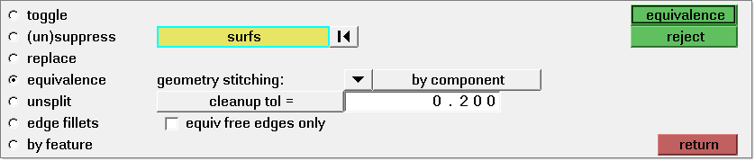
| 2. | Open the Edge Edit panel. |
| 3. | Open the equivalence subpanel. |
| 4. | Select surfs and from the extended selection menu, select all. |
| 5. | Ensure that the equiv across comps option is check marked ON. This will ensure that equivalencing of the surface edges between different components will be performed. |
| 6. | Ensure that the equiv free edges only option is check marked OFF. Turning this option OFF will ensure that equivalencing between shared edges will be performed helping to identify potential Non-manifold edges (yellow edges). |
| 7. | Click the green equivalence button to combine any edge pairs within the specified cleanup tolerance. |
Most of the red free edges are combined into green shared edges. The few remaining are caused by gaps larger than the cleanup tolerance.
| 8. | Click return to close the panel. |
|
| 1. | Open the Defeature panel. |
| 2. | Open the duplicates subpanel. |
| 3. | Click surfaces >> displayed. |
| 4. | In the cleanup tol = field, type 0.20. |
| 5. | Click find. The status bar displays the following message, "2 surfaces are duplicated". |
| 6. | Click delete to remove any duplicate surfaces. |
| 7. | Click return to close the panel. |
|
| 1. | Open the Surfaces panel. |
| 2. | Click the spline/filler  icon. icon. |
| 3. | Deselect the keep tangency check box. |
The keep tangency option looks at surfaces attached to the selected edges and tries to create a surface tangent to them. This helps to form a smooth transition to the surrounding surfaces.
| 4. | Ensure the entity type is set to lines. |
| 5. | Ensure the auto create (free edges only) check box is selected. |
The auto create option simplifies the selection of the lines bounding the missing surface. Once a line is selected, HyperMesh automatically selects the remaining free edges that form a closed loop, and then create the filler surface.
| 6. | Zoom into the area indicated in the following image. |
| 7. | Pick one of the red lines bounding one of the holes. HyperMesh automatically creates a filler surface to close the hole. |
| 8. | Repeat step 7 to create filler surface in the all gaps around the model. |
|
Use the topology display and shaded modes to perform this task. All of the edges in the model should be displayed as green shared edges, indicating that we have a completely enclosed thin solid part.
Click return to go to the main menu.
|
Once the cleanup operations are completed, save the model.
|
Return to Metal Extrusion Tutorials