Use the Mesh Style subpanel to specify the meshing algorithm to use for each face of each domain when you are following a surface-based approach. The shape of the icon on each face identifies the algorithm that has been specified for that face.
This subpanel lets you change the mesh style (quads, trias, mixed) for individual, specific surfaces.
| • | Toggle a surface to cycle through element types: tria, quad, mixed, right-tria, or quad-only. |
| • | Toggle a surface to cycle through mesh mapping methods: autodecide, rectangle, triangle, pentagon, circle, free (unmapped). |
| • | Set a surface, or all surfaces, to use any combination of options: align flow, size control, skew control, or automatic smoothing |
Panel Inputs
Input
|
Action
|
elem type: toggle surf
|
When this button is highlighted, the element type used on each surface displays as an icon in its center. Clicking the icon cycles through the available types: tria, quad, mixed, right-tria, or quad-only:
|
set surf
|
When highlighted, this button works in conjunction with the element type selected from the switch below it, setting any surface that you click to the element type specified in the switch.
|
set all
|
This button works in conjunction with the element type selected from the switch below it, setting all visible surfaces to the element type specified in the switch.
|
quads / trias / mixed / r-trias / quads only
(switch)
|
Use this switch to pick an element type that you wish to apply to some (set surf) or all (set all) surfaces.
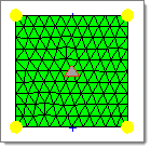
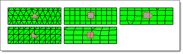
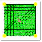
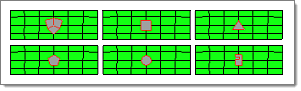
Trias
|
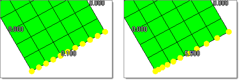
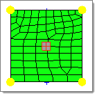
Mixed (density 10 at top,
density 5 at bottom)
|
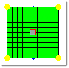
Quads
|
Right-trias
|
Quads-only (density 10
at top, 5 at bottom)
|
| Note: | In certain cases quads may still use a small number of tria elements when the mesh quality using only quads would not be acceptable. Quads only never uses trias, regardless of the resulting mesh quality.
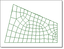
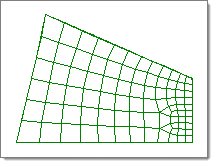
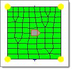
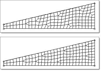
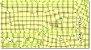
If you use the mixed (quads and trias) element type, the automesher uses a modified map as rectangle meshing scheme. The modification makes transitions between differing element densities through the use of triangles as shown below. This tends to produce mesh patterns that are more regular in appearance, as shown in the bottom image below: |
|
mesh method: toggle surf
|
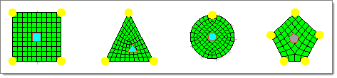
When this button is highlighted, the meshing method used on each surface displays as an icon in its center. Clicking the icon cycles through the available mapping types: autodecide, rectangle, triangle, pentagon, circle, or free:
|
mesh method: set surf
|
When highlighted, this button works in conjunction with the mesh method selected from the switch below it, setting any surface that you click to the element type specified in the switch.
|
mesh method: set all
|
When highlighted, this button works in conjunction with the mesh method selected from the switch below it, setting all surfaces to the element type specified in the switch.
|
autodecide /
map as rectangle /
map as triangle /
map as pentagon /
map as circle /
free (unmapped)
(switch)
|
This sets how the mesh will be mapped to the surface based on the surface's general overall shape.
| Note: | When using autodecide, the mesh mapping method will change automatically to one of the other types after clicking the mesh button. This is because autodecide literally chooses the best option from the other types before the mesh is applied.
Even if you do not use autodecide, the meshing engine may change the mapping method if it is clearly inappropriate for the surface being meshed. For example, it will not apply triangular mapping to a uniformly square surface, but instead will change the mapping method to triangular. |
|
set: set surf
|
When highlighted, this button works in conjunction with the various options listed below it, setting any surface that you click to use the options specified.
|
set: set all
|
When clicked, this button works in conjunction with the various options listed below it, setting all surfaces to use the options specified.
|
to use: flow: align
|
Produce a more orthogonal quad-dominant mesh. Only applies to mixed element type.
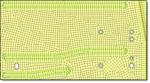
Here, there is no flow alignment
Flow alignment is used, producing straighter rows of elements
|
to use: flow: size
|
Appears only when align is active, and enforces the global mesh element size with minimal variation from the min/max element size.
|
to use: map: size
|
Keeps the elements roughly the same size.
|
to use: map: skew
|
Prevents the mesh from producing highly-skewed elements.
|
to use: smoothing
|
Performs an automatic cleanup pass on the generated mesh in an effort to improve the overall element quality.
|
local view
|
The local view pop-up menu contains tools that are customized for use in the Automeshing Secondary panel. Many of the display options are similar to those found on the View menu accessed from the toolbar. All the options orient the view, keeping the current surface centered in the window. You may also choose to suppress the display of nodes and elements.
| Location: | density, algorithm, type, biasing, details, and checks subpanels of the Automeshing Secondary panel. |
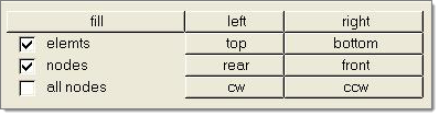
Local view pop-up menu (regular version)
The details and checks subpanels contain an expanded local view pop-up menu with additional tools. Use these tools to change the view with the focus staying centered on the highlighted face. You may also suppress the display of nodes or elements separately for the highlighted face and for the remaining faces of the surface.
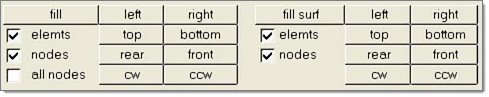
Local view pop-up menu (expanded version)
The options on the local view menu are summarized below:
cw, ccw
|
Rotates the view clockwise or counterclockwise around the center of the surface, ignoring everything else in the HyperMesh database.
|
left, right, top, bottom, rear, front
|
Sets the view to look from that direction, and then fills the screen with the surface.
|
fill surf
|
Sizes the selected surface to fill the screen.
|
elemts, nodes, all nodes
|
Controls the display of elements and nodes.
|
Comments
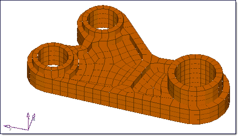
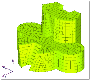
The ability to hide elements of other faces is particularly useful when you have a complicated surface with several faces and the some surfaces are interfering with your view.
Alternatively, it is sometimes helpful to display all the elements of the other faces and hide those of one face. In this way, you can look inside a complicated object.
|
|