Manufacturing Solutions

Automesh Panel

Automesh Panel

Previous topic Next topic Expand/collapse all hidden text  

Automesh Panel

Previous topic Next topic JavaScript is required for expanding text JavaScript is required for the print function  

Panel Usage


The options in the panel can be set in any order that you feel comfortable using. Moving from subpanel to subpanel will not cause you to lose work. When finished making all your selections, start the meshing process using the mesh button on the right side of the panel.

Set the panel mode by selecting the appropriate subpanel
Select the meshing method by setting the entity selector to surfs or elems
Make the required element criteria settings
Set any algorithm options
Select the area to be meshed using the entity selector and any extended selection methods desired.
Note:The unmeshed and failed selection buttons on the right side of the panel can be used to make pre-defined surface selections if desired.

panel_automesh


Subpanels and Inputs


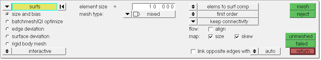
The Automesh panel contains the following subpanels:

hmtoggle_arrow1Size and Bias

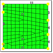
Size and bias meshing is a very flexible and powerful meshing method. A minimum of inputs are required for the element criteria settings. The algorithm options can set preferences on how to handle certain situations when encountered in the geometry. When using existing finite elements as the basis for mesh generation, feature recognition settings allow the mesher to break up the areas defined by the selected elements into logical groupings with mesh controls set for each group boundary. This meshing mode works interactively or automatically. In interactive mode, a great deal of manual control is presented via the Secondary Automesh panel during the mesh generation stage. Interactive meshing allows you to control mesh size and element type, and to set different mesh generation algorithms and test element quality on a surface-by-surface basis. The resulting modified mesh can be updated at any time, giving immediate feedback as to the effectiveness of the change. When meshing in the automatic mode, the mesh will be generated using only the settings, criteria and options set in the Automesh panel.

Size and biasing produces a mesh with consistent element size. If meshed interactively, the number of elements (element density) node spacing (biasing), element type and mesh style can be modified for each surface face and edge.


Panel Inputs

Input

Action

entity selector

Set to use surfaces or existing finite elements to define the area to mesh. Extended entity selection options are available to populate the selection.

features

When using existing finite elements as a basis for automeshing, feature recognition is used to define logical faces.  Use this switch to determine how the automesher treats features:

connected features detects features based on the specified feature angle and make additional effort to void any "orphan" or non-closed feature lines.  It works similarly to auto detect features, but includes a more rigorous check to combine small areas and avoid creating features that end abruptly or do not connect to any other features.

automesh_not_connected

Before re-meshing

automesh_connected_features

After re-meshing with connected features selected

auto detect features detects features based on the specified feature angle.
feature edges requires you to select surface edges to preserve as features.
lines requires you to manually select lines in geometry to preserve as features.
surface edges automatically detects and utilizes the geometric lines associated with the selected elements as features in the re-meshing operation.

automesh_not_connected

Before re-meshing

automesh_surface_edges

After re-meshing with surface edges selected

mesh mode toggle - interactive / automatic

Interactive mode exposes the interactive Automeshing secondary panel once the meshing has started.

Automatic mode uses only the settings and selections made in the panel to complete the meshing process.

element size

Enter a floating point numeric value for the average element size. The length of any active (shared or free) surface edge will be divided by this number to determine the number of elements to place along that edge.

mesh type

Select quads, trias, mixed, R-trias, Quads only, or advanced to specify the type of element to use in building meshes.

Mixed uses quads primarily, but inserts trias when making density transitions, resulting in improved mesh quality.

mesh_style_mixed

Quads attempts to use quads only--however, at least one tria element must be created if the sum of the element densities around the perimeter of the face or surface is odd.

mesh_style_quads_default

The sum of element densities on the perimeter of the
lower surface is odd, resulting in a tria as indicated.

Adjusting the element densities while meshing interactively can usually elimate all tria elements.

mesh_style_quads_adjusted

Adjusting the bottom edge density from 11 to 10 makes
the sum even and generates all-quads.

Quads only uses a subdividing routine that tends to generate more orthogonal quad elements.

mesh_style_quads_only

Tria elements may still be introduced depending on the density settings as with the quads type.

Tria elements uses all-trias to mesh.

mesh_style_trias

R-trias are right-angle triangular elements.

mesh_style_rtrias

If you select Advanced, choose any of the other types individually for mapped elements (elements on surfaces that can be mapped to simple geometric shapes) and free elements (those that cannot easily map to simple shapes).

AdjutA

mapped type

Choose the type of elements (as for Mesh type above) to use for surfaces that can be mapped to simple geometric shapes.

map_as_circle_free

map as circle - free

map_as_circle_mapped

map as circle - mapped

map_as_rect_free

map as rectangle - free

map_as_rect_mapped

map as rectangle - mapped

map_as_pent_free

map as pentagon - free

map_as_penta_mapped

map as pentagon - mapped

free type

Choose the type of elements (as for Mesh type above) to use for surfaces that cannot be mapped to simple geometric shapes.

feature angle

Specify a maximum angle across which elements can be maintained.

Any time two adjacent elements’ normals would exceed this angle, a new set of nodes is created between them to maintain clean feature lines.  Using a higher value results in elements spanning the feature line:

automesh_mesh_featureangle30

With an appropriate value, the features lines are preserved.

automesh_mesh_featureangle60

If the feature angle is too high, the feature lines are blurred.

vertex angle

When using connected features or auto detect features, this setting is a maximum element vertex angle.  Whenever an element vertex exceeds this angle while adhering to features, the element will be split into two elements with correspondingly smaller vertices.

elems to surf comp / elems to current comp

Select the destination component for the newly created elements as the “current” active component or the component to which the surface belongs. The current component is indicated in the component list of the Model browser, or the component status display of the status bar.

first order /second order

Set to create first order (linear shape function) or second order (polynomial shape function) elements.

connectivity

Select how the connectivity between the newly created elements and any adjacent existing elements will be handled. Choices include:

keep connectivity: use the existing nodes on any shared boundary edges.
redo connectivity: re-seeds any existing nodes along the boundary of the newly created mesh to optimize mesh quality.
break connectivity: ignore any existing adjacent elements and generate the mesh according to the size and type specified.
previous settings: re-use any previous node density and spacing settings associated to the selected surface edges.

flow: align

Produce a more orthogonal quad-dominant mesh. Only applies to mixed element type.

flow_align1

Here, there is no flow alignment

flow_align2

Flow alignment is used, producing straighter rows of elements

flow: align produces a more orthogonal quad dominated mesh
flow: size appears only when align is active, and enforces the global mesh element size with minimal min/max element size variation.

map: size

Keeps the elements roughly the same size.

map: skew

Prevents the mesh from producing highly-skewed elements.

anchor nodes

Designate nodes that will remain and be re-used in the new mesh.  Anchor nodes are "fixed" so that the automesher cannot move or replace them; in essence, they are exceptions to the re-meshing operation, and the new mesh must utilize them.

link opposite edges with AR <

Links mesh settings on opposing edges of rectangular surfaces. Use the toggle to define the maximum aspect ratio (AR) to allow between large and small edge sizes of linked edges. auto corresponds to a value of 2.11. Increasing the value will add more surfaces to the linked chain, whereas decreasing the value will remove some surfaces from the linked chain.

density_link_edges_before

Mesh without link opposite edges

with AR < selected.

density_link_edges_after

Mesh with link opposite edges

with AR < set to auto.

arequal8

Mesh with link opposite edges

with AR < set to 8.0.


hmtoggle_arrow1batchmesh/QI optimize

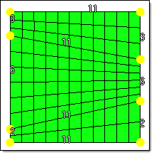
Quality Index meshing is an iterative automatic mesh generation method driven by element quality criteria. During the mesh generation process, the quality index of the mesh is determined by evaluating each element against a set of element quality tests.  If all required element quality criteria are passed, then that element has a perfect quality index of zero. As the element quality deteriorates, the quality index value increases; so a lower quality index score indicates an element more closely meets the ideal quality requirements.

The compound quality index sum of the quality index values for each of the elements included in the current meshing area. The quality index value itself has no direct physical meaning; it is a way to compare one generated mesh pattern against another pattern generated for that same area. The quality index based mesh optimization routine attempts to modify the mesh pattern and apply node smoothing routines to obtain a lower overall quality index value.

For more information on element quality index, refer to Quality Index calculations.


Panel Inputs

Input

Action

batchmesh/QI optimize toggle

Toggles between QI optimize meshing parameters and BatchMesh parameters.

entity selector

Set to use surfaces or existing finite elements to define the area to mesh.  Extended entity selection options are available to populate the selection.

features

The automesher will seed nodes along features so as to avoid spreading elements across them.  When the entity selector is set to elems, use this switch to determine how the automesher treats features:

connected features automatically detects features based on the specified feature angle and make additional effort to void any "orphan" or non-closed feature lines.  It works similarly to auto detect features, but includes a more rigorous check to combine small areas and avoid creating features that end abruptly or do not connect to any other features.

automesh_not_connected

Before re-meshing

automesh_connected_features

After re-meshing with connected features selected

auto detect features automatically detects features based on the specified feature angle.
feature edges requires you to select surface edges to preserve as features.
lines requires you to manually select lines in the geometry to preserve as features.
surface edges automatically detects and utilizes the geometric lines associated with the selected elements as features in the re-meshing operation.

automesh_not_connected

Before re-meshing

automesh_surface_edges

After re-meshing with surface edges selected

element size

Enter a floating point numeric value for the average element size. The length of any active (shared or free) surface edge will be divided by this number to determine the number of elements to place along that edge.

mesh type

Select quads, trias, mixed, or Quads only to specify the type of element to use in building meshes.

Mixed uses quads primarily, but inserts trias when making density transitions, resulting in  improved mesh quality.

mesh_style_mixed

Quads attempts to use quads only--however, at least one tria element must be created if the sum of the element densities around the perimeter of the face or surface is odd.

mesh_style_quads_default

Adjusting the element densities while meshing interactively can usually eliminate all tria elements.

mesh_style_quads_adjusted

Quads only uses a subdividing routine that tends to generate more orthogonal quad elements.

mesh_style_quads_only

Tria elements may still be introduced depending on the density settings as with the quads type.

Tria elements uses all-trias to mesh.

mesh_style_trias

Use current criteria / Criteria file:

Use this toggle to choose between using the current element quality criteria or specifying a criteria file that has been previously created. When set to use current criteria, the green edit criteria button is presented.

Edit criteria

This button only displays when use current criteria is selected, and opens the Criteria File Editor.

feature angle

Specify a maximum angle across which elements can be maintained.

Any time two adjacent elements’ normals would exceed this angle, a new set of nodes is created between them to maintain clean feature lines.  Using a higher value results in elements spanning the feature line:

automesh_mesh_featureangle30

With an appropriate value, the features lines are preserved.

automesh_mesh_featureangle60

If the feature angle is too high, the feature lines are blurred.

vertex angle

When using connected features or auto detect features, this setting is a maximum element vertex angle.  Whenever an element vertex exceeds this angle while adhering to features, the element will be split into two elements with correspondingly smaller vertices.

Smooth across common edges with

Node smoothing moves nodes across adjacent surface edges whose feature angle is less than the value specified. When selected, strict adherence to the geometry of the surface edges in not enforced for non-feature edges; some deviation from the geometry can occur.

elems to surf comp / elems to current comp

Select the destination component for the newly created elements as the “current” active component or the component to which the surface belongs. The current component is indicated in the component list of the Model browser, or the component status display of the status bar.

first order /second order

Set to create first order (linear shape function) or second order (polynomial shape function) elements.

connectivity

Select how the connectivity between the newly created elements and any adjacent existing elements will be handled. Choices include:

keep connectivity: use the existing nodes on any shared boundary edges.
redo connectivity: re-seeds any existing nodes along the boundary of the newly created mesh to optimize mesh quality.
break connectivity: ignore any existing adjacent elements and generate the mesh according to the size and type specified.
previous settings: re-use any previous node density and spacing settings associated to the selected surface edges.

flow: align

Produce a more orthogonal quad-dominant mesh. Only applies to mixed element type.

flow_align3

Here, there is no flow alignment

flow_align4

Flow alignment is used, producing straighter rows of elements

flow: align produces a more orthogonal quad dominated mesh
flow: size appears only when align is active, and enforces the global mesh element size with minimal min/max element size variation.

anchor nodes

Designate nodes that will remain and be re-used in the new mesh.  Anchor nodes are "fixed" so that the automesher cannot move or replace them; in essence, they are exceptions to the re-meshing operation, and the new mesh must utilize them.

preserve edges

Opens the Preserve Edges tool, from which you can use to ensure that specific components edges and feature lines do not accidentally get discarded during autocleanup or batch meshing.


hmtoggle_arrow1Edge Deviation

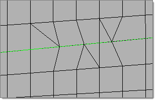
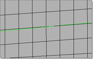
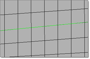
Use the Edge Deviation subpanel to set specific meshing parameters to limit how far the mesh elements can deviate from the actual edges of the surfaces meshed, or when in the case of re-meshing elements, deviation from inferred edges based on features.

Controls for the minimum and maximum allowable element size, edge deviation and maximum angle are introduced with this method.  Edge deviation normally occurs on curved edges, because individual elements have straight edges and therefore can only approximate a curve.

automesh_edge_deviation_example

When meshing curved surfaces as shown here, the planar elements (tan color) can deviate from the curved grey geometry.

Edge deviation applies to both surface geometry and when re-meshing elements. Automeshing on the edge deviation subpanel automatically selects the best element size to approximate a curve, within the limits that you specify. The max deviation and max angle settings are the primary controls for this effect.

Note:This differs from the size and bias subpanel, which only meshes with elements of a uniform size that you specify.

This method can produce a mesh in which the element size varies, even within the same surface. Areas of high curvature will tend to have smaller elements than areas of low or no curvature. The element size boundaries controls this effect.

automesh_edge_deviation_mesh_example

Edge deviation control when meshing creates smaller elements and spaces nodes closer together to limit how much the elements can deviate from the surface edges.

Panel Inputs

Input

Action

entity selector

Set to use surfaces or existing finite elements to define the area to mesh.  Extended entity selection options are available to populate the selection.

features

The automesher will seed nodes along features so as to avoid spreading elements across them.  When the entity selector is set to elems, use this switch to determine how the automesher treats features:

connected features automatically detects features based on the specified feature angle and make additional effort to void any "orphan" or non-closed feature lines. It works similarly to auto detect features, but includes a more rigorous check to combine small areas and avoid creating features that end abruptly or do not connect to any other features.

automesh_not_connected

Before re-meshing

automesh_connected_features

After re-meshing with connected features selected

auto detect features automatically detects features based on the specified feature angle.
feature edges requires you to select surface edges to preserve as features.
lines requires you to manually select lines in the geometry to preserve as features.
surface edges automatically detects and utilizes the geometric lines associated with the selected elements as features in the re-meshing operation.

automesh_not_connected

Before re-meshing

automesh_surface_edges

After re-meshing with surface edges selected

mesh mode toggle - interactive / automatic

Interactive mode will expose the interactive Automesh panel once the meshing has started.

Automatic mode does not allow the mesh to be modified after it is created.

min / max element size

Specify the element size boundaries. The values specified here are rigidly enforced, even if other settings (that is max deviation) are violated.

max deviation

The allowable deviation between the element edge and the surface edge. To meet this requirement, element edge lengths along a curved surface edge are reduced as needed down to a lower limit set by the min elem size field.

max angle

Defines the maximum allowable angle between two element edges.  This also helps determine the size of an element to create; if the angle formed by adjacent element edges would exceed this value, smaller elements are tried until the angle is equal to or less than this value.

mesh type

Select quads, trias, mixed, R-trias, Quads only, or advanced to specify the type of element to use in building meshes.

Mixed uses quads primarily, but inserts trias when making density transitions, resulting in  improved mesh quality.

mesh_style_mixed

Quads attempts to use quads only--however, at least one tria element must be created if the sum of the element densities around the perimeter of the face or surface is odd.

mesh_style_quads_default

Adjusting the element densities while meshing interactively can usually eliminate all tria elements.

mesh_style_quads_adjusted

Quads only uses a subdividing routine that tends to generate more orthogonal quad elements.

mesh_style_quads_only

Tria elements may still be introduced depending on the density settings as with the quads type.

Tria elements uses all-trias to mesh.

mesh_style_trias

R-trias are right-angle triangular elements.

mesh_style_rtrias

If you select Advanced, choose any of the other types individually for mapped elements (elements on surfaces that can be mapped to simple geometric shapes) and free elements (those that cannot easily map to simple shapes).

Tria

mapped type

Choose the type of elements (as for Mesh type above) to use for surfaces that can be mapped to simple geometric shapes.

map_as_circle_free

map as circle - free

map_as_circle_mapped

map as circle - mapped

map_as_rect_free

map as rectangle - free

map_as_rect_mapped

map as rectangle - mapped

map_as_pent_free

map as pentagon - free

map_as_penta_mapped

map as pentagon - mapped

free type

Choose the type of elements (as for Mesh type above) to use for surfaces that cannot be mapped to simple geometric shapes.

feature angle

Specify a maximum angle across which elements can be maintained.

Any time two adjacent elements’ normals would exceed this angle, a new set of nodes is created between them to maintain clean feature lines.  Using a higher value results in elements spanning the feature line:

automesh_mesh_featureangle30

With an appropriate value, the features lines are preserved.

automesh_mesh_featureangle60

If the feature angle is too high, the feature lines are blurred.

vertex angle

When using connected features or auto detect features, this setting is a maximum element vertex angle.  Whenever an element vertex exceeds this angle while adhering to features, the element will be split into two elements with correspondingly smaller vertices.

elems to surf comp / elems to current comp

Select the destination component for the newly created elements as the “current” active component or the component to which the surface belongs. The current component is indicated in the component list of the Model browser, or the component status display of the status bar.

first order /second order

Set to create first order (linear shape function) or second order (polynomial shape function) elements.

connectivity

Select how the connectivity between the newly created elements and any adjacent existing elements will be handled. Choices include:

keep connectivity: use the existing nodes on any shared boundary edges.
redo connectivity: re-seeds any existing nodes along the boundary of the newly created mesh to optimize mesh quality.
break connectivity: ignore any existing adjacent elements and generate the mesh according to the size and type specified.
previous settings: re-use any previous node density and spacing settings associated to the selected surface edges.

flow: align

Produce a more orthogonal quad-dominant mesh. Only applies to mixed element type.

automesh_noFlowControl2

Here, there is no flow alignment

automesh_FlowControl2

Flow alignment is used, producing straighter rows of elements

flow: align produces a more orthogonal quad dominated mesh
flow: size appears only when align is active, and enforces the global mesh element size with minimal min/max element size variation.

map: size

Keeps the elements roughly the same size.

map: skew

Prevents the mesh from producing highly-skewed elements.

link opposite edges with AR <

Links mesh settings on opposing edges of rectangular surfaces. A control is available to define the maximum aspect ratio (AR) to allow between large and small edge sizes of linked edges. auto corresponds to a value of 2.11. Increasing the value will add more surfaces to the linked chain, whereas decreasing the value will remove some surfaces from the linked chain.

density_link_edges_before

Mesh without link opposite edges

with AR < selected.

density_link_edges_after

Mesh with link opposite edges

with AR < set to auto.

arequal8

Mesh with link opposite edges

with AR < set to 8.0.

anchor nodes

Designate nodes that will remain and be re-used in the new mesh.  Anchor nodes are "fixed" so that the automesher cannot move or replace them; in essence, they are exceptions to the re-meshing operation, and the new mesh must utilize them.


hmtoggle_arrow1Surface Deviation

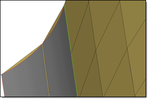
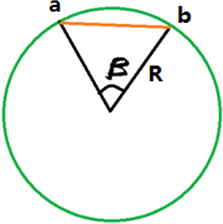
This subpanel is only accessible when meshing surfaces.  Use the Surface Deviation subpanel to mesh within limits of element deviation from a surface.

Similarly to the edge deviation subpanel, meshing behavior on this subpanel is driven by distances between flat elements and model geometry.  When flat elements are used to approximate a curved surface, there is always a discrepancy between each element and the actual curve of the surface, because the element uses a straight line between two nodes:

automesh_surfacedeviation

A gap is visible between the curved edge of the surface and the element edges.

The surface deviation automesh method chooses the mesh density based on the severity of this deviation.  Where the threshold deviation would be exceeded, smaller elements are used to reduce the deviation:

automesh_surfacedeviation_example

With surface deviation meshing, smaller elements are used to accurately represent curved surfaces. Larger elements are used where the geometry shows less curvature.

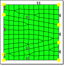
The surface deviation meshing works only in an automatic mode; interactive meshing with the secondary automesh panel is not possible. However, use the refine function to set a specific desired mesh size for a point, line or surface face. This option accesses another temporary subpanel that is slaved to the surface deviation subpanel. From this subpanel, select fixed points, lines, or surfaces to define an area in which you desire a more refined mesh. You can specify a different element size for these areas, which displays as a color-coded numeric value: yellow for points, green for lines, or red for surfaces.  An option to show all or show active toggles the view of these numeric values; show active displays only the refinement value for the most recently selected point, line or surface, while show all shows all values for all selected entities.

After specifying refinement options, click mesh to create a smoothly-scaled mesh from your base element size to the size specified in the refine options.

surface_deviation_refine_before

Here, the mesh is not refined, but the colored numbers indicate refinement targets: point (yellow), line (green), and surface (red)

surface_deviation_refine_after

Here, refinement is applied.  You can see that the mesh is finer near the point (yellow), along the line/edge (green), and on the surface (red).

Panel Inputs

Input

Action

entity selector

Set to use surfaces or existing finite elements to define the area to mesh.  Extended entity selection options are available to populate the selection.

element size

Enter a floating point numeric value for the average element size. The length of any active (shared or free) surface edge will be divided by this number to determine the number of elements to place along that edge.

growth rate

Determines how rapidly elements can increase in size as they are created further and further away from features.

automesh_growthrate

Elements further from the features grow larger with each row.

min elem size

Elements with edges smaller than this value will not be created.

span angle

Controls the element size at curve input. The smaller the angle, the more refined curvature will be and the more preserved the input shape will be. By default span angle is 25.0 degrees.

In the green circle below, β is the span angle of the edge ab. The length of ab is less than 2R( sin β/2 ).

span_angle

Valid only for element-based surface deviation.

feature angle

Determines which features to preserve. The mesher identifies features internally and preserves/refine them based on the defined feature angle.

Valid only for element-based surface deviation.

max deviation

The allowable deviation between the element edge and the surface edge. To meet this requirement, element edge lengths along a curved surface edge are reduced as needed down to a lower limit set by the min elem size field.

max feature angle

Specify a maximum angle across which elements can be maintained.

Any time two adjacent elements’ normals would exceed this angle, a new set of nodes is created between them to maintain clean feature lines.  Using a higher value results in elements spanning the feature line:

automesh_mesh_featureangle30

With an appropriate value, the features lines are preserved.

automesh_mesh_featureangle60

If the feature angle is too high, the feature lines are blurred.

mesh type

Select quads, trias, mixed, R-trias, Quads only, or advanced to specify the type of element to use in building meshes.

Mixed uses quads primarily, but inserts trias when making density transitions, resulting in  improved mesh quality.

mesh_style_mixed

Quads attempts to use quads only--however, at least one tria element must be created if the sum of the element densities around the perimeter of the face or surface is odd.

mesh_style_quads_default

Adjusting the element densities while meshing interactively can usually eliminate all tria elements.

mesh_style_quads_adjusted

Quads only uses a subdividing routine that tends to generate more orthogonal quad elements.

mesh_style_quads_only

Tria elements may still be introduced depending on the density settings as with the quads type.

Tria elements uses all-trias to mesh.

mesh_style_trias

R-trias are right-angle triangular elements.

mesh_style_rtrias

If you select Advanced, choose any of the other types individually for mapped elements (elements on surfaces that can be mapped to simple geometric shapes) and free elements (those that cannot easily map to simple shapes).

mapped type

Choose the type of elements (as for Mesh type above) to use for surfaces that can be mapped to simple geometric shapes.

map_as_circle_free

map as circle - free

map_as_circle_mapped

map as circle - mapped

map_as_rect_free

map as rectangle - free

map_as_rect_mapped

map as rectangle - mapped

map_as_pent_free

map as pentagon - free

map_as_penta_mapped

map as pentagon - mapped

free type

Choose the type of elements (as for Mesh type above) to use for surfaces that cannot be mapped to simple geometric shapes.

elems to surf comp / elems to current comp

Select the destination component for the newly created elements as the “current” active component or the component to which the surface belongs. The current component is indicated in the component list of the Model browser, or the component status display of the status bar.

first order /second order

Set to create first order (linear shape function) or second order (polynomial shape function) elements.

connectivity

Select how the connectivity between the newly created elements and any adjacent existing elements will be handled. Choices include:

keep connectivity: use the existing nodes on any shared boundary edges.
redo connectivity: re-seeds any existing nodes along the boundary of the newly created mesh to optimize mesh quality.
break connectivity: ignore any existing adjacent elements and generate the mesh according to the size and type specified.
previous settings: re-use any previous node density and spacing settings associated to the selected surface edges.

closed volume proximity

Dynamically create finer mesh across the narrow spaces between features in a closed volume/solid entity.

This feature is essentially the same as the combination of use curvature and use proximity in the Tetramesh panel, except that it creates a 2D surface mesh instead of a 3D tetramesh.

free edge deviation

Produce finer mesh around curved edges (such as holes) even on planar surfaces.

When unchecked, meshing is based on surface chordal deviation only.

refine

Opens a temporary subpanel, from which you can perform mesh refinement on or around specific points, lines, or surfaces:

Use the switch to select the type of entity to use as a basis, then select the points/lines/surfaces and specify an element size in the numeric box.

Show refined

If you use refine to perform localized mesh refinement, this check box displays the refinement element size you assigned to each entity marked for refinement.


hmtoggle_arrow1Rigid Body Mesh (surface meshing only)

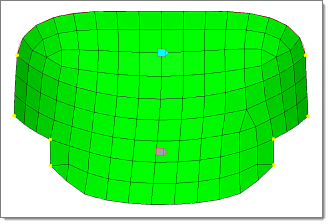
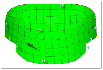
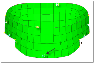
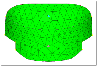
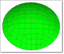
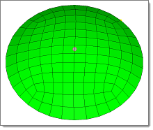
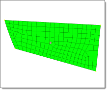
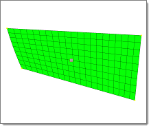
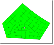
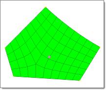
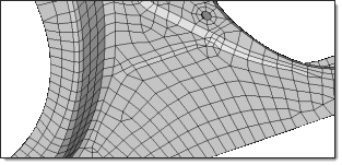
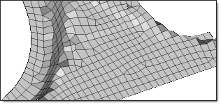
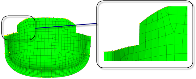
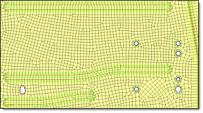
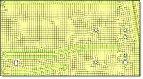
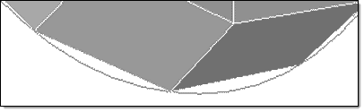
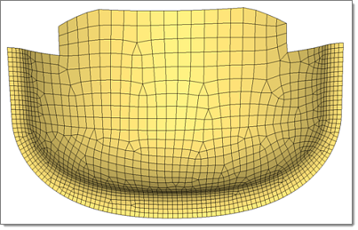
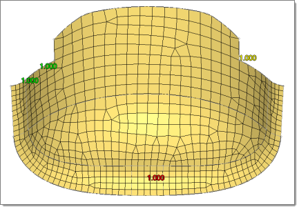
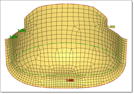
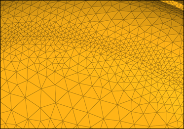
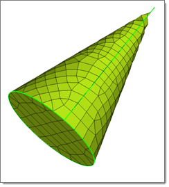
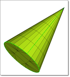
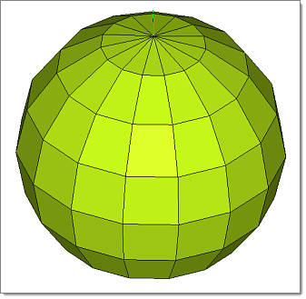
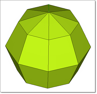
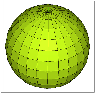
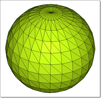
Use the Rigid Body Mesh subpanel to create a quick mesh to represent the topology of a rigid object. Only the automatic meshing mode is available.

Rigid bodies are surfaces that are expected to be treated as undeformable in the solution.  One example of a rigid body is in metal-forming.  When modeling the results of a die pressing down on a metal sheet, it’s important to model the shape of the die because that determines the shape of the metal sheet after being pressed.  However, during a forming analysis the stresses and deformations of the die itself are not of interest, only those of the formed metal sheet. Other applications for rigid bodies include the impactors used in vehicle crash simulation.

A mesh that accurately represents the rigid geometry is important for such simulations to allow the solver collision detection routines to work effectively and accurately.  Since stress and deformation of the rigid body are not calculated by the solver, the rigid body mesh focuses on accurately modeling the shape of the body rather than on producing a high-quality mesh.  To this end, it uses the same faceting and shading routines that are used for drawing the model graphics. The resulting mesh may have high aspect ratio or extremely tapered elements that would not be suitable for solution, but can accurately represent the geometry.

The images below illustrate the differences between surface deviation meshing and rigid body meshing. Both meshes were generated using the same parameters in terms of min/max element size, maximum deviation and feature angle, and mesh type.

automesh_rigidbody_surrfacedevexample

When creating a surface deviation based mesh on this cone, many small elements are required to capture the geometry, even so, the elements exhibit a lot of warpage and those at the tip are distorted and do not accurately represent the geometry.

automesh_rigidbody_rigidexample

With the rigid body mesh, the shape of the object can be accurately modeled using fewer larger elements since the element shape is not a concern.

Panel Inputs

Input

Action

entity selector

Set to use surfaces or existing finite elements to define the area to mesh. Extended entity selection options are available to populate the selection.

min / max elem size

Specify the element size boundaries. The values specified here are rigidly enforced, even if other settings (i.e. max deviation) are violated.

max deviation

The allowable deviation between the element edge and the surface edge. To meet this requirement, element edge lengths along a curved surface edge are reduced as needed down to a lower limit set by the min elem size field.  See the images fro max feature angle below for more detail.

max feature angle

Specify a maximum allowable break angle between adjacent elements. The element size is adjusted such that the angle between the normals of adjacent elements does not exceed this value.

surf_dev_deviation_bound_mesh


In these examples, the minimum and maximum element sizes are 3 and 50  respectively. In this first image, the mesh is constrained by the max deviation value set to 0.5. The element size is set such that the maximum distance between the element and the spherical surface does not exceed this setting.

surf_dev_deviation_anglebound_mesh


In this second example, the deviation setting is relaxed to 3.0, and the mesh is bound by the maximum feature angle setting of 45 degrees.

mesh type

Select trias or mixed to specify the type of element to use in building meshes.

Mixed uses quads primarily, but uses trias din areas where the mesh converges uses quads primarily, but uses trias  In areas where the mesh converges.

surf_deviation_mixed

Tria elements uses all-trias to mesh.

surf_deviation_trias

elems to surf comp / elems to current comp

Select the destination component for the newly created elements as the “current” active component or the component to which the surface belongs. The current component is indicated in the component list of the Model browser, or the component status display of the status bar.

first order /second order

Set to create first order (linear shape function) or second order (polynomial shape function) elements.


See also

Alphabetical List of Panels

HM-3100: AutoMeshing

HM-3120: 2-D Mesh in Curved

HM-3130: QI Mesh Creation