This tutorial shows you how to set up and run a one-step analysis from the RADIOSS One Step user profile. The HyperForm interface for incremental analysis if featured in later tutorials.
Files for this Tutorial
Die_Mesh.hm
Tutorial Overview
| • | Session 1: Fundamental HyperForm user interface |
| • | Session 2: Using the online help |
| • | Session 3: File input and output |
| • | Session 4: The concept of collector |
| • | Session 5: Secondary menus |
| • | Session 6: Default HyperForm files |
Exercises
Three exercises are provided in this chapter:
Exercise 1: Opening a database file and using the tool bar
Exercise 2: Understanding Collectors and using online help
Exercise 3: Translating elements
Session 1: Fundamental HyperForm user interface
The HyperForm window consists of these main areas: the graphics area, the User Process tab, the header bar, the main menu, Utility Menu, and the drop-down menu. You can access secondary menus either through their main panel or by using keyboard function keys.
User profiles
The HyperForm user interface includes the following analysis configurations:
| • | RADIOSS One Step: Setup, run, and review of a one-step analysis |
| • | Incremental_RADIOSS: Setup and run an incremental analysis using RADIOSS Solver |
| • | Die Module: Create and edit binders and addendums |
| • | Incremental_LS-DYNA: Setup and run an incremental analysis using the LS-DYNA solver |
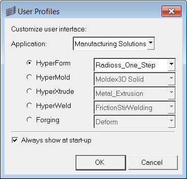
After starting HyperForm, the following dialog appears.

In the Application: field, select Manufacturing Solutions and then select one of the modules - RADIOSS One Step, Incremental_RADIOSS, Incremental_LS-DYNA, or Die Module - before performing any further operations.
The selected configuration can include loading a specific template, loading a specific Utility menu, renaming panels, removing unused panels or subpanels, and removing, moving, or renaming panel options. The selected configuration can change the appearance of a panel, but they do not affect the internal behavior of each function.
Graphics Area
The graphics area displays geometry, models, and XY plots.
Status Bar
The status bar is located at the bottom of the HyperForm window, just below the user profile switches on the Utility menu. It displays the name of the current panel and user profile, and model status information. Messages also appear on the message bar, temporarily overriding the title and status information.
Using the Mouse
The mouse attached to your system is integral to HyperForm and can be used in almost every aspect of user input. A two- or three-button mouse can be used with HyperForm.
The mouse buttons have these functions:
Left mouse button
|
Performs selection operations.
|
Right mouse button
|
De-selects entities in the graphics area. Aborts graphics operations.
|
Middle mouse button
|
In the rotate (r) and arc dynamic motion (a) modes, selects a new center of rotation when you pick a node in the model.
|
CTRL + left mouse button
|
Dynamically rotates the model
|
CTRL + the middle mouse button
|
Zooms into an area of the model
|
CTRL + the right mouse button
|
Pans the model
|
Toolbars
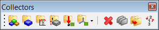
Collectors toolbar
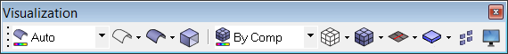
Visualization toolbar
Display toolbar
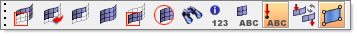
The toolbars enable you to manipulate the view of the model, control which collectors are displayed in the graphics area, set global modeling parameters, and edit solver-specific data.
The functions of some of the toolbar menu icons are described below:
Panel
|
Icon
|
Description
|
Files
|

|
Load, save, or import files.
|
Card edit
|

|
Edit solver-specific data in card format
|
Wireframe Elements
|

|
Draws model geometry as a wire-frame
|
Shaded Elements & Mesh Lines
|

|
Draws model geometry in shaded mode
|
Wireframe geometry
|

|
Draws model geometry as a wire-frame. Click the downward arrow to choose between excluding and including surface lines.
|
Shaded Geometry & Surface Edges
|

|
Draws model geometry in shaded mode. Click the downward arrow for options: with edges or without them.
|
Visualization
|

|
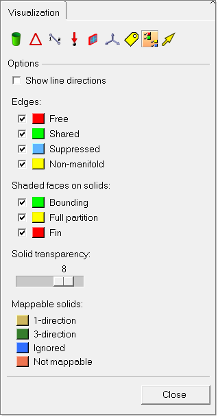
Show or hide different types of topology, connector, or morphing entities. A sub-menu is enabled when this panel is selected.
|
The following viewing icons are available:
Item
|
Icon
|
Description
|
Previous View
|

|
Returns to the previous view
|
Fit Model
|

|
Resizes the model view to fit the model to the graphics area
|
Modal Zoom
|

|
Circle zoom (left-click) / Dynamic zoom (right-click).
Left-clicking activates the circle zoom feature. Circle zoom deactivates after zooming once, or when you click either button while the pointer is in the graphics area.
Right-clicking activates the dynamic zoom feature. Once active, right-click and drag in the graphics area to zoom in/out. Left-click to deactivate.
|
Incremental Zoom
|

|
Zoom incrementally; left-click to zoom in, right-click to zoom out
|
Rotate Mode
|

|
Rotate modes: this functions in one of two different ways:
Left-click to activate dynamic rotate mode. Once active, click-and-drag in the graphics area to rotate the model. Right-click to deactivate.
Right-click to activate dynamic spin mode. Once active, right-click in the graphics area and hold the mouse button down to make the model spin. Left-click to deactivate.
|
Pan modes
|

|
Pan modes: this functions in one of two different ways:·
Left-click to activate pan mode. Once active, click-and-drag in the graphics area to pan the model view. Right-click to deactivate.
Right-click to activate center mode. Once active, right-click in the graphics area to change the graphics area center. Left-click to deactivate.
|
Rotate (left/right)
|

|
Click the left mouse button to rotate the model leftward, and the right button to rotate it rightward.
|
Rotate (up/down)
|

|
Click the left mouse button to rotate the model upward, and the right button to rotate it downward.
|
Exercise 1: Opening a database file and using the toolbar
Step 1: Load the HyperForm RADIOSS One Step environment file
| 2. | On the Preferences menu, click User Profiles…. |
| 3. | For Application, select Manufacturing Solutions. Verify that HyperForm and RADIOSS One Step are selected. |
Step 2: Load the model file
| 1. | From the File menu, select Open. |
| 2. | In the Open File dialog, change the Files of type field to All files. |
| 3. | Navigate to Die_Mesh.hm, and click Open. |
Note: The model files for this tutorial are located in the file mfs-1.zip in the subdirectory \hf\1Step\. See Accessing Model Files.
Step 3: Change the visualization of the model
| 1. | In the Model browser, expand the Master Model folder, and then Component folder. |
| 2. | Right-click on the Binder component and select Hide. Notice the Binder mesh is no longer displayed in the graphics area. Right-click on it again and select Show. |
| 3. | From the toolbar, click the Shaded Elements & Mesh Lines icon to re-draw the model geometry in shaded mode. |
| 4. | From the toolbar, click the Wireframe Elements icon to re-draw the model geometry in wireframe mode. |
| 5. | From the toolbar, click the Element Color Mode icon  and select By Mat from the selection list. and select By Mat from the selection list. |
Notice that the Binder and Addendum components become a gray color. This indicates the two components share the same material.
| 6. | Repeat step 5 and change the setting back to By Comp. |
| 7. | From the Preferences menu, click Colors. |
| 8. | The graphics area is displayed as a gradient color. You can change both the lighter and darker colors. Click the color box next to Background 1 and Background 2 and select other color options. This changes the background color to your selection. |
| 9. | Click Reset to restore the default settings. |
| 10. | Click Close to close the dialog. |
| 11. | From the toolbar, right-click Pan modes . |
| 12. | Move the mouse cursor to graphics area, keep on holding the right mouse button and pan the model graphically. |
Move the mouse cursor back to toolbar menu to release the panning action.
Note: Pan action can also be achieved by holding Ctrl keyboard + right mouse button.
| 13. | From the toolbar, left-click Rotate Mode icon to enter dynamic rotate mode. |
| 14. | Click and drag in the graphics area to rotate the model. |
| 15. | From the toolbar, left-click Incremental Zoom icon to zoom in on the model. |
| 16. | From the toolbar, click Fit View icon to fit the model on the screen. |
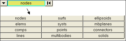
Main Menu
From the main menu you can access to a variety of panels grouped by the selected user profile.
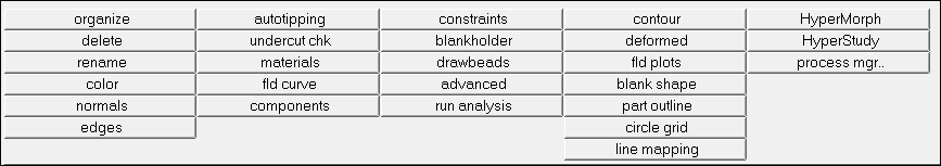
The main menu with the RADIOSS One Step user profile loaded
Toggles and Switches
Toggles and switches allow you to select and specify options that need to be determined before you complete the function.

|
Click a toggle to alternate between two options.
|

|
Click a switch to display a list of options in a pop-up menu.
|

|
Reset button. This removes selection and back to empty value
|
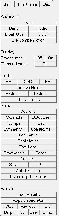
Utility Menu
The Utility menu is located on the left side of the graphics region and can be relocated by clicking View > Tab Area. When Manufacturing Solutions and HyperForm working environments are loaded, the Utility menu is automatically switched to the HyperForm working environment. It provides tools for defining/reviewing/editing a model. The Model tab option enables the Model browser functionality.
The user profile selection buttons are at the bottom of the menu.
1Step
Quick access/switch to the RADIOSS One Step user profile
RADIOSS
Quick access/switch to the Incremental_RADIOSS user profile
Die
Quick access/switch to the Die Module user profile
Disp
Tools for visualization purpose
Util
Utilities to perform operations at geometry level.
User
User-created macros only
Dyna
Quick access/switch to Incremental_LS-DYNA user profile
To hide the Utility menu:
From the View menu, uncheck the Utility menu.
To display the Utility Menu:
From the View menu, check the Utility menu.
|
|
The Menu Bar
The menu bar, located just beneath the title bar, enable access to many types of functionality. Most menu options access panels, but some options perform other tasks such as configuring the layout of the HyperForm environment.

When the HyperForm environment is loaded, the menu bar also enables you to access to the fundamental menus regardless of the customization of the HyperForm interface.
Session 2: Using the online help
HyperForm includes a help system to provide information about using the interface. There are several methods of accessing and using the online help system.
Method 1: Start online help from the pull-down menu
This method provides access to all information.
| 1. | Stay in the main menu; do not click any panel. |
| 2. | From the Help menu, select HyperForm. The HyperForm online help is launched. |
This book contains all information including Release Notes, User’s Guide, Reference Guide, Tutorials, etc.
Method 2: Start context-sensitive help
This method allows you to search information specifically for individual panels.
| 1. | Click any panel from the main menu, for example, the Sections panel, and stay in the selected panel. |
| 2. | From the keyboard, press the H key. This directly enters the help function for the selected panel. The information for the Sections panel is displayed on screen. |
Method 3: Finding information using the tabs
You can also search information by typing any keyword(s).
| 1. | Stay in the main menu; do not click any panel. |
| 2. | From the Help menu, select HyperForm. |
| 3. | Click on the Index or Find tab, and type in the desired keyword(s). A list of related topics is displayed. |
Session 3: File input and output
File input and output is performed through the File menu.
Option
|
Description
|
File - Open/Save/ Save As
|
Saves and retrieves HyperForm binary database files.
There are no restrictions placed on HyperForm database file extension names other than those imposed by the operating system.
To load a HyperForm database file on top of another HyperForm database file (*.hf ), use the import option.
|
File - Import
|
Loads CAD generated geometry or finite element model information.
It is possible to import a CAD generated geometry or a finite element model information file into a HyperForm database file.
| • | HF PARM translator is used to import one step analysis ASCII input file |
|
File - Export
|
Writes an ASCII file in a format specific to the selected analysis code.
|
Load
|
Load a the template file used to format the HyperForm database for a specific analysis code, or load a Results file, or a Macro file.
|
Run
|
Run a command file or a TCL script
|
Session 4: The Concept of a Collector
Collectors store entities, grouping together all the data pertaining to an entity and allowing you to handle the data as a group. Collectors in HyperForm consist of the Components, Materials and Sections (for Incremental_RADIOSS and Incremental_LS-DYNA analysis) panels.
The component and material collectors in HyperForm have specific data associated with them. In one-step analysis, the component collector contains thickness data while the material collector holds the Young’s Modulus of Elasticity value and other constants.
All entities in a HyperForm database are stored in collectors. Based on the analysis type, each collector may use a dictionary or card image to define the attributes assigned to the collector.
The Collectors panel allows you to create and update collectors and assign and edit card images or dictionaries. Before you build a model, create a component collector for storing or organizing different data.
Exercise 2: Understanding collectors and using online help
The Die_Mesh.hm file from Exercise 1 should still be loaded in HyperForm.
In steps 1 through 6, you will practice changing the visualization of component collectors.
| 1. | In the Model browser, click on the Mesh  icon next to the Part component to turn off the display of the mesh for that component. Notice the mesh of the Part component is no longer displayed in the graphics area. The surface of the Part component is still visible. icon next to the Part component to turn off the display of the mesh for that component. Notice the mesh of the Part component is no longer displayed in the graphics area. The surface of the Part component is still visible. |
| 2. | Click the Mesh icon to turn the mesh display back on. |
| 3. | Similarly, click the Geometry icon next to the various components to turn their display on and off. When finished, right-click on the Components folder and click Show to display all of the components completely. |
In steps 4 though 11, you will review card images, assign a new material to the Part component, and use the online help.
| 4. | From the Application menu, select Incremental_RADIOSS. |
| 5. | From the main menu, click the Components panel. |
| 6. | Double-click component: and select Part. The associated material is displayed. Notice material = Rigid_material. |
| 7. | Click edit card to review the card image in solver definition. |
| 8. | Click return to go back to the Components panel. |
| 9. | Click material: and select CRDQ Steel material. |
| 10. | Click update. Notice the associated material is now changed to CRDQ Steel. |
| 11. | Press the H key to start the online help. The online help is launched, displaying the help topic for the panel. Review information for the Components panel. Return to the main menu when finished. |
Session 5: Secondary Menu
The secondary menu contains several stand-alone functions, like calculating the distance between two points. Accessing the secondary menu interrupts the active main panel and allows you to perform a function from the secondary panel and then return to the main panel. For example, a user can access the secondary menu by pressing the function keys, F1 through F12, Shift F1 through shift F12, and more.
Menu Items
The menu items on each panel allow you to specify settings and enter information that is needed to perform the panel’s function. Panels can contain subpanels, function buttons, toggles, switches, entity selectors, direction selectors, data entry fields, input fields, and pop-up menus.
In the following discussion of menu items, you will be using the Translate panel. Access it from the Geometry menu.
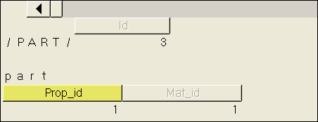
Entity Selector
The entity selector allows you to choose the type of entity to be modified when performing a function. The entity selector may or may not have a switch  ; some panels perform a function on only one type of entity. The entity selector button is yellow; when it is surrounded by a blue box, the collector is active and ready for you to select or pick the entities to be processed. You can click on the switch to change the entity selector type.
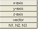
Direction Selector
The direction selector allows you to define a plane or vector by using the global x, y, or z axis, or by selecting a vector, or by selecting nodes in the database.
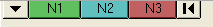
|
Direction selector pop-up menu
|
|
x-, y-, and z-axis
|
Specify a direction along any one of the global axes.
|
vector
|
Use a pre-existing vector entity (something you can create using the Vector panel) to define a direction.
|
N1, N2, N3
|
Create a user-defined direction. Selecting two nodes, N1 and N2, allows you to define a vector direction with base point at N1 toward N2. Selecting three nodes, N1, N2, and N3, allows you to define a plane with base point at N1 (unless otherwise specified). The vector is normal to the plane and its direction is determined by the right hand rule.
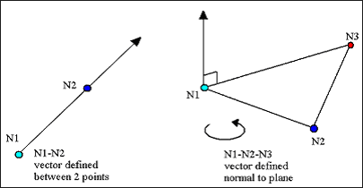
Direction vectors for 2 point and 3 point definitions
|
Reset 
|
Clears the node selections.
|
Input Fields
Input fields are used to enter text or numerical values. A description of the type of input precedes the field.

For numeric input fields, you can use the keyboard to enter the value or double-click the input field and use the pop-up calculator to enter the value.
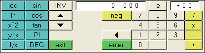
An example to input values and operations is as below:
"0.0 (default) + 6" will need to be inputted as 0.0(default), 6, +, enter
Pop-up Menus
Pop-up menus display when there are several options from which to choose.
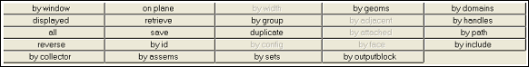
For example, the extended entity selection menu (shown below) allows you to specify alternate methods for selecting entities of the current data type. To use the extended entity selection menu, click the yellow data type button of the entity selector. The menu automatically closes when you have made your selection.
Notice the grayed-out options within the pop-up menu indicates that the function is disabled in the selected entity selection menu.
Function Buttons
The color of the menu button corresponds to its purpose:
Green Carries out a function or a command.
Red Exits a panel or aborts a command.
Exercise 3: Translating Elements
The Die_Mesh.hm file from the previous exercise should still be loaded in HyperForm.
Access the Translate panel by hot keys
| 1. | From the Geometry menu, select Translate. |
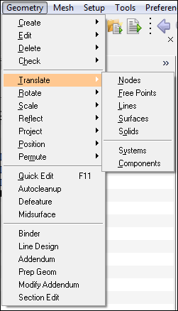
All selections under the Translate option are displayed. SHIFT + F4 is the hot key for the Translate function.
| 2. | Press SHIFT + F4 to access the Translate panel directly. |
Select the elements to translate
| 1. | Click the entity selector switch . A pop-up menu is displayed, listing all the entity types that can be modified with the Translate panel. The mouse cursor is located at the center of the pop-up menu. |
| 2. | Select elems to specify "elements" as the entity type you want to translate. |
After you select elems, the pop-up menu automatically closes. The yellow entity selector button displays "elems" and the button has a blue border to indicate that it is active.
| 3. | Click elems. The extended entity selection menu displays, with the mouse cursor in the center. |
| 4. | Select by collector to indicate you want to select the elements by component collector. After you select by collector, a list of component collectors is displayed. |
| 5. | In the graphics area, pick a cyan element by clicking near its element handle (the dot in the center of the element). Selecting this element also selects the component collector containing the element, Part in this case. |
The element picked is momentarily highlighted white. The check box preceding Part has a white check mark in it.
| 6. | Click select to select all the elements in the component collector, Part, as the elements to be modified when you use the translate function. |
The Translate panel again displays and all of the elements in the Part component are highlighted.
Specify a direction to translate the selected elements
| 1. | Click the direction selector switch. A menu is displayed with a list of plane and vector options for translating the selected entities. The mouse cursor is located at the center of the pop-up menu. |
| 2. | Click N1 N2 N3 to select the N1, N2, N3 method. The pop-up menu automatically closes. |
The blue border around N1 indicates it is active. The selected elements in the graphics area are now gray because the entity selector is not active.
| 4. | In the graphics area, pick a node. A green circle displays in the graphics area at the node that was picked. The N1 button no longer has a blue border, but the N2 button does. N2 is currently active. |
| 5. | In the graphics area, pick any other node. A blue circle displays in the graphics area at the node you specified. The N2 button no longer has a blue border, but the N3 button does. N3 is currently active, but in this case, a node for N3 will not be specified. |
| 6. | In the graphics area, right-click the blue circle to deselect the node N2. The blue node N2 is not displayed in the graphics area. The N2 button now has a blue border. |
| 7. | In the graphics area, pick a different node. This new node is the new N2 node. A blue circle displays in the graphics area at the node you specified. |
Specify a distance to translate the selected elements
| 1. | Double-click magnitude =. The calculator pop-up menu appears. |
| 2. | Input 50.0, click ENTER and click exit to leave the calculator. |
| 3. | Click translate +. The highlighted elements move 50 units in the positive N1-N2 vector direction with N1 being the vector’s base node and the vector passing through N2. |
| 4. | Click reject to reject the translation action. |
| 5. | Click f on the keyboard. The model is resized to fit the screen. |
Session 6: Default HyperForm Files
HyperForm includes or automatically creates several default files. These include:
hm.cfg
|
configuration file
|
hmmenu.set
|
user interface settings
|
command.cmf
|
command file
|
hm.cfg
The hm.cfg file is a default configuration file read on start-up. The hm.cfg file controls many aspects of how HyperForm runs at your particular site. You can edit the commands in the hm.cfg file to your own preferences.
command.cmf
The command.cmf file is a standard ASCII file that HyperForm reads and writes. Command files allow you to retrieve a work session in case of a system crash or program a series of procedures. You can use a command file in applications that contain repetitive steps or you can create demonstrations.
All commands executed by the HyperForm command processor are written to this file. This file is automatically created in the directory in which you started HyperForm. If the file already exists, new commands are appended to the existing file.
For more information about the command.cmf file, please see the HyperForm online help topic HyperForm Commands.
hmmenu.set
The hmmenu.set file is a binary file that HyperForm updates when you exit HyperForm. Your personal hmmenu.set file stores many global parameters and is located in the directory from which you started HyperForm. If the file already exists, it is overwritten after you run a new session. The most recent global parameter values in the current HyperForm session are written to this file when you exit. The next time you start HyperForm, it has the values recorded in the hmmenu.set file. If the file does not exist when HyperForm is invoked, the global parameter values are default values.
Return to HyperForm Tutorials


