|
»Click here to display Table of Contents«
|

|
Feed Design |

|

|

|

|
|
|
Feed Design |
|
|

|

|
Feed Design
|
»Click here to display Table of Contents«
|
|
Feed Design |
|
|
|
|
|
|
Feed Design |
|
|
|
|
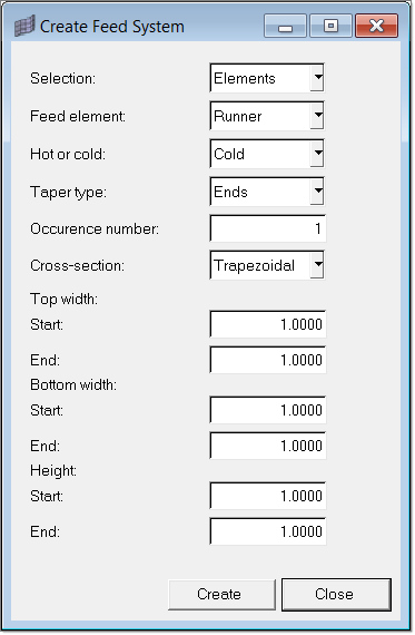
The Create Feed System macro assists in creating a feed system (also known as runner system). This macro creates property cards for the selected elements that make the runner system and supports all the beam elements that make up the feed system and the associated taper/cross-section options. The following options are available in the Create Feed System dialog:
Feed Element: |
Element can be of one of the following types: Sprue, Runner, or Gate. Depending on the selection, the cross-section option could take different values. For instance, Moldflow allows only a circular section of cold sprue. |
|
Hot or cold: |
This option takes the value Hot or Cold. In the UDM format, different element cards support them. That is, two different property cards define cold sprue and hot sprue. However, while exporting it in MPI 2.0 format, this is identified by the color of element. This issue is handled internally. |
|
Taper type: |
The taper type can be one of the following: None, Ends, or Angle. For None there is no taper. If the taper is specified using Angle, the starting dimension and the taper angle is specified. For Ends, dimensions at both ends of the element selection should be specified. The taper is applied to all the elements in the selection and the macro prompts you to enter the starting element. The elements in the selection must be continuous. |
|
Occurrence number: |
Defines the symmetry in the multi-cavity mold. See About Occurrence Numbers for more details. |
|
Cross-section: |
Feed elements can have one of the following shapes as the cross-section: Circular, Annular, Half-circular, Trapezoidal, Other-shape, or Rectangular. There are restrictions on the shapes taken by sprue: cold sprue can be circular and hot sprue can be circular or annular. These are restrictions in Moldflow. |
|
Dimension: |
Based on the taper and cross-section choices, the dimension entries are resized and displayed. |
|
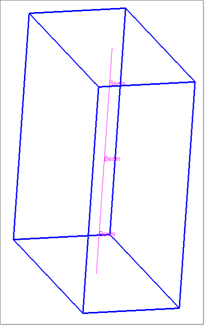
Besides creating the property cards, the macro also creates solids to highlight the shapes. It should be noted that shapes supported are half-circular, trapezoidal, circular, rectangular and annular. Also, the coupling between the surfaces and elements is a weak coupling. That is, deleting the element or solid will not delete the other. It will be redrawn only if the properties are altered through the macro.
Click Edit Solid Data to select a feed solid to edit. The feed data given during the creation of the solid is populated in the Edit Feed System dialog. You can change the values and click Update to set the new values to the feed solid. If multiple solids are selected, then the first solid is considered for editing.
Click Edit Element Data to select an element whose property card you want to edit. Once you select an element, the associated property’s name and type appear in a popup dialog. Click Update and the property’s card image opens for editing in the main menu area, where you can change the values in the fields for that property.
- Draw your feed system using lines.
|