| 1. | In the tree of the Die Process browser, select Addendum Start Line, right-click and select Auto. |
An addendum start line is created in component ^Die1_ASL1. This component is assigned to ASL1.
| 2. | In the tree, select Binders, right-click and select New. |
A new object, Binder 1, is created and appears on the tree.
| 3. | In the tree, select Binder1, right-click and select Create > Flat. |
| 4. | In the panel that appears, click below the part as you see in the following figure: |
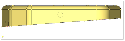
| 5. | For Offset, enter 150.0, and then click Create. |
| 6. | To exit the panel, click Return. |
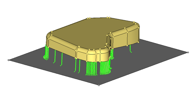
| 7. | In the white space of the Die Process browser, right-click, and from the context menu, select Contour > Draw Depth > With Binder. |
As you see in the following figure, a contour image appears providing maximum draw depth:
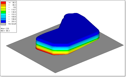
Locate the Maximum and Minimum value. In next step you translate the binder until the minimum value is 30 mm.
| 8. | On the panel, click Return. |
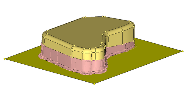
| 9. | In the tree of the Die Process browser, select Binder1:Die1_Binder1, right-click, and then select show. |
The binder display that was hidden while creating the contour returns.
| 10. | Select Binder1:Die1_Binder1, right-click, and then select edit. |
| 11. | In the new panel that appears, do the following: select Manipulate binder; select the box for translate; for axis, select Z-axis; for the magnitude value, subtract 30 from the minimum value that you observed in Step 7; click translate +; click return. |
| 12. | To recheck the draw depth, repeat the actions from Step 6. |
|
| 1. | In the tree of the Die Process browser, under Die1, select Addendum > New. |
A new object, Addendum 1, is created. The binder created in the previous step is assigned to Addendum 1 establishing a relationship between the two parts.
| 2. | Select Addendum1, right-click, and select Create > Single section. |
| 3. | In the panel that opens, do the following: for line selector, pick the Addendum start line that you created in the previous step; for surface selector, pick the binder that you created in the previous step. |
| 4. | Click Rib Editor, and the following interface appears: |
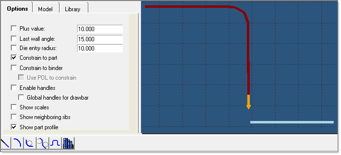
The Rib Editor is a two-dimensional interface for use in the design of parametric cross-sections of an addendum. These cross sections are known as ribs. A rib can be constructed from one or multiple basic shapes known as segments. After designing a rib, you can add it to a model. You can also construct an addendum surface using all of the ribs created.
| 5. | Verify that only Constrain to part and Show part profile are activated. If Show part profile is off, click the Options tab, and next to the Show part profile option, select ON. |
The part profile is displayed as a red-dotted section line.
| 6. | On the viewing options bar, right-click zoom-out  twice. twice. |
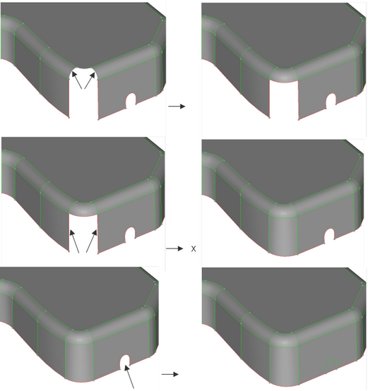
| 7. | Press the Ctrl key, and with the left mouse button draw a circle in the plot area to zoom into the area shown in the following figure: |
Note: You can also draw the circle by clicking Circle Zoom  from the viewing options. from the viewing options.
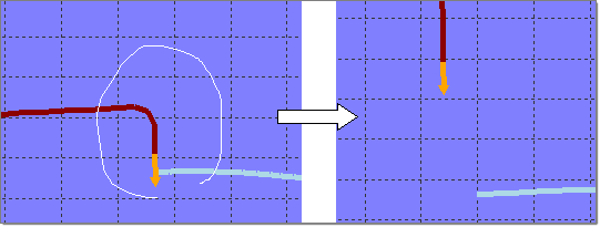
The part profile (red), part edge tangency (orange arrow) and the binder profile (light blue) are displayed.
| 8. | Click the Append button. |
The status action mode : Append is displayed above the action buttons enabling you to add any new shape to the part edge tangency.
| 9. | To append a Half S section to the end of the part, on the tool bar, click Half S  . . |
A straight-line section tangent to the edge of the part is added as you see in the following figure:
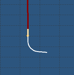
Notice the two parameters, Length and Angle, are defined in the parameter display area. Also notice the current action mode is still set to Append. The Append mode ensures that any new rib created will be added to the end of the currently highlighted section. You can change the action mode to Insert, Replace or Delete, however for this exercise, continue with the action mode set to Append.
| 10. | Select the box, Constrain to binder. |
| 11. | For Radius, enter 15.0, and then press the Enter key. |
| 12. | Click the Options tab. To enable modification to the rib sections, next to Enable handles, select ON. |
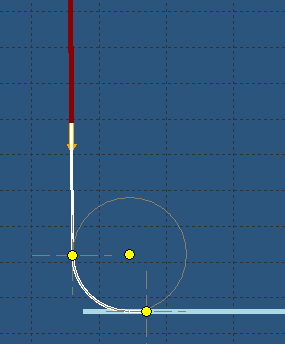
Handles turned ON
You can apply graphical changes to the ribs as required.
| 13. | Left-click and hold, and move the cursor to the top of the handle. |
Notice the handle changes to red. In addition, the plot area displays the message: Fillet of Half S shape Radius: 15.0.
| 14. | Keep holding the left mouse button and drag the cursor. Notice the value of the radius change. |
| 15. | Once the rib is defined, to close the Rib Editor window, click return. HyperForm remembers the shape of the rib and applies it when you create the addendum. |
| 16. | To generate the ribs, click create ribs. Ribs are generated as you see in the following figure: |
| 17. | To create the addendum surface, click create addendum. |
You have completed this tutorial!
|
|