The addendum is the part of the die face that facilitates the smooth and controlled flow of metal into the die cavity.
This tutorial shows you how to use the Die Process utility to create a basic addendum. The process includes constructing a binder; building an addendum that connects the part and binder surface; and trimming the binder to get a complete die cavity.
Prerequisites
This tutorial assumes that you are familiar with basic HyperMesh functions such as creating components, geometry cleanup, and meshing. For information on these topics, see the online help.
Files for this Tutorial
cup_addendum.hf.
| 1. | From the File menu, click Open. |
| 2. | Navigate to the model file cup_addendum.hf. |
Note: The model files for this tutorial are located in the file mfs-1.zip in the subdirectory \hf\Die\. See Accessing Model Files.
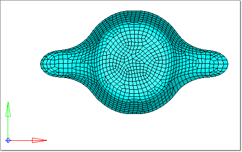
The model loads and looks something like this:
|
| 1. | In the tree of the Die Process browser, under Settings, right-click Symmetry > Edit. The Symmetry Setting panel appears. |
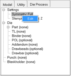
| 2. | In the panel, set the Symmetry toggle to full (default). |
| 4. | From the toolbar, select Preferences > HyperForm Settings. |
| 5. | In the dialog that appears, select the ProcessDefaults tab. |
| 6. | For BinderDepth, enter 10.0. |
| 7. | For BinderOffset, enter 50.0. |
| 8. | Click Apply, then Close. |
|
| 1. | In the tree of the Die Process browser, under Dies > Die1, right-click Part: (none) and select Set.... |
| 2. | Select the part from the model graphics, and click proceed. |
Note that the name of the component appears in front of the label Part. For this example, Part: Die1 appears. A copy of the selected part is made in component Die1 to create the die surface. Also the outer boundary of the part is automatically determined and assigned as the trim line.
|
| 1. | In the tree of the Die Process browser, under Dies > Die1, right-click Addendum Start Line, and then select Auto. |
The addendum start line is automatically added to the component ^Die1_ASL1 and assigned to the object, Addendum start line.
| 2. | Under Dies > Die1, right-click Binder, and then select Create. |
A new object, Binder1, is created and the ASL created in the previous step is assigned to it.
| 3. | Right-click Binder1, and then select Create > From Part: |
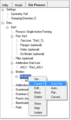
The binder surface is created in the component, Die1_Binder1, and is assigned to Binder1.
|
| 1. | In the tree of the Die Process browser, under Die1, right-click Addendum, and then select New. |
A new object, Addendum1, is created and the binder created in the previous step is assigned to it.
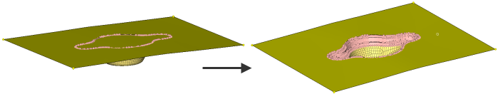
| 2. | Right-click Addendum1, and then select Create > From Part. |
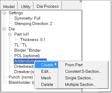
The addendum is created in a temporary collector, ^Addendum, and assigned to the object, Addendum1.
|
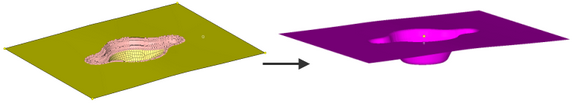
| 1. | In the white space of the Die Process browser, right-click, and then select Trim Binder > With Addendum: |
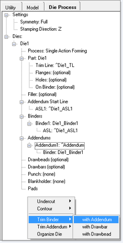
| 2. | To see the cavity more clearly, rotate the model. |
|
| 1. | In the tree of the Die Process browser, right-click Punch: (None) and select By Offsetting Part and Addendum…. |
| 2. | Enter a value for the offset. The offset distance is the gap between the punch and the die, which should be equal to the blank thickness + 20 percent of blank thickness. |
| 3. | Based on the direction of the vector, click Offset. |
The punch is created in a collector named Punch. The object punch in the Die Process tree reflects the name of the punch component.
| 5. | Right-click Blank Holder: (None), and select By Offsetting Binder…. |
| 6. | For Offset, enter a value. |
The offset distance is the gap between the punch and the die, which should be equal to blank thickness + 20 percent of the blank thickness.
| 7. | Based on the direction of the vector, click Offset. |
The Blankholder is created in a collector named Blank holder. The object Blank holder in the Die Process tree reflects the name of the Blank holder component.
It is advised to keep the blank ready by using tools in the Part Feasibility module prior to creating tools. You can also switch to the Incremental_RADIOSS user profile and use the functions Auto Process and/or User Process to setup the solver parameters for RADIOSS Incremental.
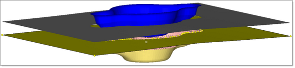
Punch and binder with the die
| 9. | To organize all of the elements and surfaces into one component, in the white space of the Die Process browser, right-click and select Organize die. |
You have completed this tutorial!
|
Return to Die Module Tutorials


