| 1. | From the File menu, select Open. |
| 2. | Navigate to the model file die_module_ex3.hf. |
Note: The model files for this tutorial are located in the file mfs-1.zip in the subdirectory \hf\Die\. See Accessing Model Files.
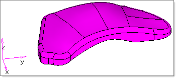
The file loads and looks something like this:
|
| 1. | From the tree in the Die Process browser, right-click Part, and from the context menu, select Set. |
| 2. | To select the part, on the model graphics, left-click, and then to accept the selection, middle-click. |
The name of the component appears in front of the label, Part. For this example, Part: Die1 appears. A copy of the selected part is made in component Die1 to create the die surface. Also the outer boundary of the part is automatically determined and assigned as a trim line.
|
| 1. | In the tree of the Die Process browser, select Addendum Start Line, right-click and select Auto. |
An addendum start line is created in component ^Die1_ASL1. This component is assigned to ASL1.
| 2. | In the tree, select Binders, right-click, and select New. |
A new object, Binder 1, is created and appears on the tree.
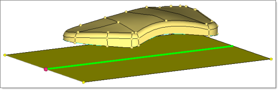
| 3. | In the tree, select Binder1, right-click, and select Create > Flat. |
| 4. | In the panel that appears, click below the part as you see in the following figure: |
| 5. | For Offset enter 150.0, and then click Create. |
| 6. | To exit the panel, click Return. |
| 7. | In the Die Process browser, select Binder1, right-click, and select Mesh. |
|
| 1. | In the tree of the Die Process browser, select Binder1, right-click, and select Edit. |
| 2. | On the panel that appears, select the binder on section > create Section. |
| 3. | For axis, select X axis from the pull down menu, and then click on the edge of the binder as you see in the image in the following step. |
| 4. | Click Create. A section of the binder is created. |
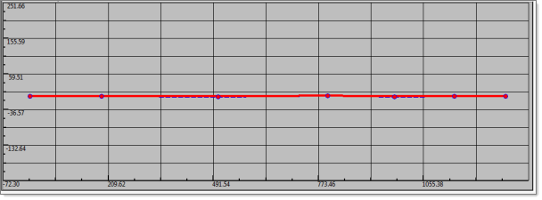
| 5. | Select edit section; for Method, select 2D; pick the line created in the previous step; and then click Edit. |
A section editor opens with a 3D view on top as you see in the following image. The section editor lets you easily create a 2D profile that you can later apply to shape the binder.
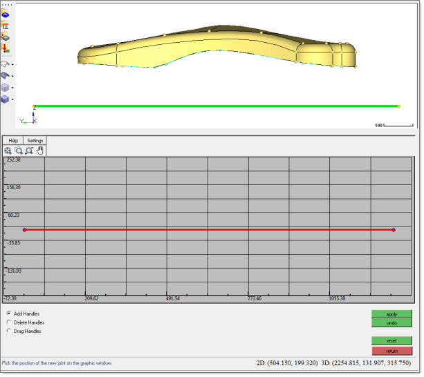
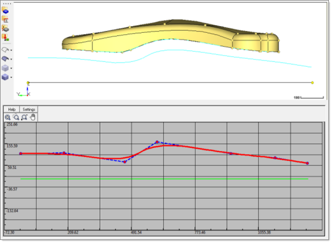
| 6. | Click the Add Handles radio button, click the red line, and then click Apply. Repeat these actions to add five points as you see in the following figure: |
| 7. | Click the Drag Handles radio button, and then left-click and drag each handle to approximate the following shape: |
| 8. | To exit the section editor, click return. |
| 9. | Select map to section, select the modified line created from the previous steps, and then click Preview. |
| 10. | Review the binder shape that appears, and if satisfactory, select Accept. |
The modified binder shape is applied. The following figure shows an approximation of what you might observe in your model:
| 11. | To exit the panel, click return. |
|
| 1. | In the tree of the Die Process browser, under Die1, select Addendums, right-click and select New. |
A new object, Addendum 1, is created, and the binder created in the previous step is assigned to it.
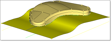
| 2. | Select Addendum1, right-click and select Create > From Part. |
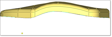
A new addendum is created with an S-section profile:
|
| 1. | In the tree of the Die Process browser, under Die1, select Addendum1, right-click, and then select Edit. |
The ribs of the addendum are highlighted and the edit panel appears.
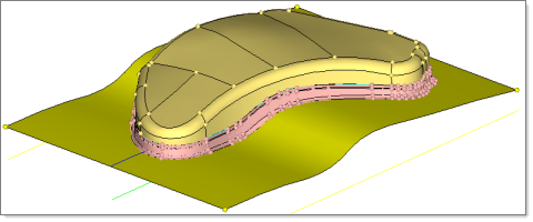
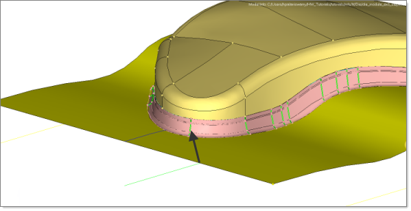
| 2. | Select edit rib parameters, and then pick a rib in the model as you see in the following figure: |
| 3. | After selecting the rib, click rib editor. |
The rib editor opens and includes the information for the selected rib.
| 4. | In the rib editor, select the Green rib, and double-click. The parameters of the rib are displayed. |
| 5. | For the Radius 1 value, enter 20, and then press the Enter key. |
| 6. | To close the rib editor, click return. |
| 7. | To update the addendum as defined, click update. |
The addendum is redrawn.
| 8. | To exit the panel, click return. |
|
| 1. | In the tree of the Die Process browser, under Die1, select Addendum1, right-click, and then select Edit. |
The ribs of the addendum are highlighted and the Edit panel opens.
| 3. | For the model line selector, pick the rib that was modified in the previous step. |
| 4. | To define the candidate to edit, click lines selector. |
| 5. | As you see in the following figure, pick the ribs adjacent to the rib modified in the previous step: |
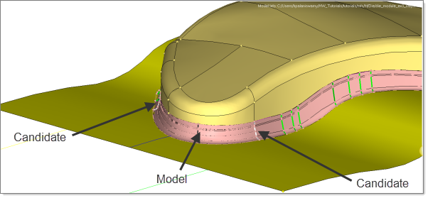
The addendum is updated as defined.
| 7. | To exit the panel, click return. |
You have completed this tutorial!
|
|


