|
»Click here to display Table of Contents«
|

Assign Thickness |

|

|

|

|
|
Assign Thickness |
|
|
|

|
|
»Click here to display Table of Contents«
|
Assign Thickness |
|
|
|
|
|
Assign Thickness |
|
|
|
|
In Moldex3D Shell user profile, thickness to the part can be assigned or extracted. If the part surface was extracted as a midsurface then the thickness information can be extracted. If the part surface is a normal surface, then the thickness information is not available and hence has to be assigned. Click Assign Thickness to display the following dialog.
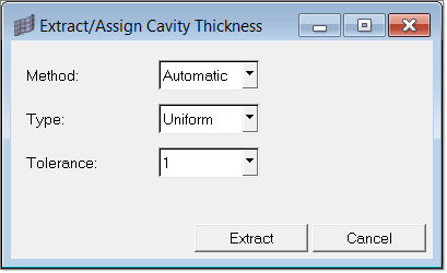
The Automatic method is valid for mid surfaces. Also the type can be selected between Uniform and Non-uniform. Moldex3D Shell provides the flexibility to specify different thicknesses at the three nodes of the tria element. Non-uniform thickness types incorporate this feature. The tolerance levels are specified in terms of number of digits after the decimal.
If the method is Manual, then an extra field to specify the thickness appears as shown below.
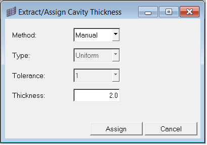
For the Manual method only Uniform type is valid. For the surface(s) selected, the elements on the surface are moved to a component named Cavity. The properties created are named such as Cavity_thickness_1.0, Cavity_thickness_2.0 and so on. This is done so that the thickness can be found out just by looking at the name itself. For non-uniform type the names would be Cavity_thickness_1_2_3, Cavity_thickness_2_1_3 and so on. The numbers signify the thickness at the three nodes of the element. After extraction/assignment, a contour is plotted depicting the thickness distribution.
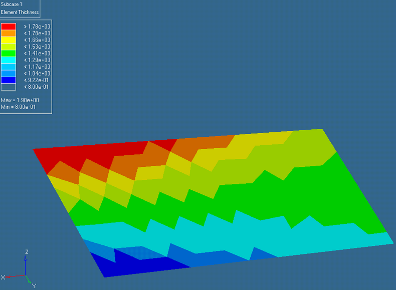
The thickness distribution can also be plotted from the Diagnostics sub menu.