Open the Subsystem Browser
Use the Subsystem Browser to create, organize and manage CAE subsystem level models using any entities.
By default, the following attributes are listed as columns.
Add or remove columns by right-clicking on a column and checking/unchecking the appropriate attribute.
- Name
- Expandable list of subsystems and entities.
- ID
- Identification number of the subsystem and entities.
- Color
- Color of the subsystem and entities.
- UID
- Subsystem and part unique ID.
- Revision
- The Major, Study, and Library revision of the subsystem and contained parts.
- Representation
- In-session and loaded representation for the subsystem.
- Active
- Subsystem entity active status.
- FE Style
- Current FE style for components inside a subsystem.
View Modes

Figure 1.
- Entity View. Displays a single view in the browser for parts or subsystems.
- Set View. Splits the browser into two views: Entity View and Set View. In the Set View you can create, organize and manage part and subsystem sets.
- Configuration View. Splits the browser into three vertical views: Configuration, Set and Entity View. In the Configuration view you can create, organize and manage configurations.
- Configuration View, Split Left. Splits the browser into three views: Configuration, Set and Entity View. In the Configuration view you can create, organize and manage part configurations and subsystem configurations.
Part View Modes

Figure 2.
- Hierarchical Part View. Displays all entities, including components, in a
hierarchical view.
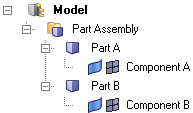
Figure 3. - Flat Part View. Displays all entities, with the exception of components, in
a flat list. Part Assemblies and Parts are logically grouped into their own
collectors.
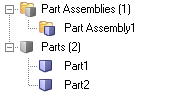
Figure 4.For example, in Flat View, you can use the Query Builder to isolate part entities. In the example BOM shown above, setting the entity type filter to Part results in the following view.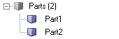
Figure 5.
Entity Editor
Display the attributes for the subsystem if selected. Edits can be made to single subsystem selections only.
Entities
Entities are listed where the entities themselves are not visible in the browser. For example, loads are displayed because the Subsystem Browser only shows load collectors.
Nodes, elements, loads, systems, vectors, and beam sections are displayed.
Each of these entities can be selected in the Entity Editor. This invokes the selection options so that you can add to or remove from the selection, updating the contents of the subsystem.
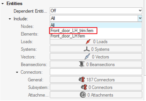
Figure 6.
Finally, entities can also be reviewed.
Dependent Entities
- Off
- The default setting. Checking dependent entities reduces the responsiveness of the selection of subsystems in the browser.
- Missing
- Missing entities occur when the entity is not present in the subsystem but was expected to be there since the parent entity was displayed. For elements and nodes, this occurs when the entity is not in the subsystem but the component is.
- Additional
- The inverse of Missing. This occurs when the entity is in the subsystem but the parent is not. For example, the node is in the subsystem but the component is not. If all entities are organized into subsystems, an entity that is additional in one subsystem will be missing from another.
- Shared
- Only nodes can be shared. This occurs when connected elements are organized into different subsystems. In this case, nodes are highlighted that join the two subsystems as shared since those nodes are the shared boundary between two subsystems.
All of the above can be reviewed. You can also Isolate to display the missing entities and then use the Entities option to correct the subsystem by selecting and organizing those missing entities.
Library and Representation Data
Library data shows the Major, Study, and Library revisions of the subsystem. It also shows the Library Name to which the representation was saved.
Representation data shows the Representation Name and the file path of the saved representation.
Organize Settings
Determine which dependent entities to move when managing subsystem content and behavior if entities are shared across subsystems.
When moving an entity into a subsystem, there are customizable options that determine which dependent entities would also be organized into the subsystem. For example, moving a component by default will also move the associated nodes, elements, properties and materials.
There are secondary options that determine the action if the entity is shared (has multiple references). For example, when moving a property, should the material should also move to the subsystem if a different property also references the same material?
When moving an include, organize settings are ignored, and only the include content is moved.
To access these settings, right-click in the Subsystem Browser and select Organize Settings from the context menu.