This task is an example of thermal analysis mapping using heat transfer coefficients
and bulk temperatures. This mapping option is available for the OptiStruct profile. CSV files or result logs
from AcuSolve can also be used as a source.
Data in a .csv file can be based on a local coordinate system.
The format of the .csv file is x, y, z, value1, value2, and so
forth. The x, y, z data can be in a global or local system , including cylindrical. Figure 1.
In the Model Browser, right-click and select Create > Field from the menu.
In the Entity Editor, edit the field's corresponding
attributes.
In the Model Browser, right-click on the field
entity and select Realize from the menu.
In the Field Realization dialog, define the realization
settings:
Select the target mesh in the Entity field.
From the Field type drop-down menu, select
convection.
From the Interpolation drop-down menu, select the appropriate
interpolation method.
Set the Normal distance and Tolerance values as appropriate.
Select the sub-case and simulation from which the heat transfer
coefficients and bulk temperatures are to be mapped.
When you are ready, click Apply.
Data is mapped to the selected structural mesh. The following solver
entries are created for the OptiStruct profile:
Group - PCONV
Heat transfer coefficient calculated during the mapping process,
stored in card: attribute:H1.
CHBDYE
Surface elements over target or base elements.
CONV
PCONV ID and arbitrary node number (TA1) created for bulk
temperature.
SPC
An arbitrary node is created and the SPC (without any DOF) is
attached to this node. Used to store the bulk temperature calculated
during the mapping process.
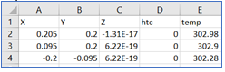 Figure 1.