Create solver seatbelt features using Control Points.
After the seatbelt mesh is realized, Control Points are defined in the browser. The Control Points context menu
allows you to select various seatbelt features and perform automatic creation.
If you are using the LS-DYNA solver:
In the Seatbelt Browser, right-click on either the
first or last control point under the appropriate seatbelt system to
display the context menu.
Select Retractor to create an
*ELEMENT_SEATBELT_RETRACTOR and its attachment to the structural
components via *CONSTRAINED_NODAL_RIGID_BODY or
*CONSTRAINED_EXTRA_NODES.
Select Retractor + Pre-Tensioner to create an
*ELEMENT_SEATBELT_RETRACTOR and an *ELEMENT_SEATBELT_PRETENSIONER and
its attachment to the structural components via
*CONSTRAINED_NODAL_RIGID_BODY or *CONSTRAINED_EXTRA_NODES.
Select Constrained Extra Node to create an
attachment between the seatbelt and a rigid structural component via a
*CONSTRAINED_EXTRA_NODES.
Select Constrained Nodal Rigid Body to create an
attachment between the seatbelt and a deformable structural component
via a *CONSTRAINED_NODAL_RIGID_BODY.
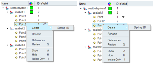
Select a Control Point that is common to two seatbelt entities,
right-click and select Create > Slipring 1D or Slipring 2D.
Sliprings allow you to create an *ELEMENT_SEATBELT_SLIPRING and its
attachment to the structural components via
*CONSTRAINED_NODAL_RIGID_BODY or *CONSTRAINED_EXTRA_NODES. Figure 1. Slipring 1D and Slipring 2D
If you are using the Radioss solver:
In the Seatbelt Browser, right-click on either the
first or last control point under the appropriate seatbelt system to
display the context menu.
Select Anchor PreTensioner to create a SPRING to
model the pre-tension effect.
Select Retractor + PreTensioner to create two
SPRINGS to model the retractor effect and the pre-tensioner
effect.
Select Retractor + PreTensioner + LL (LOAD
LIMITER) to create three SPRINGS to model the retractor
effect, the pre-tension effect, and the load limiter effect.
Select a Control Point that is common to two seatbelt entities,
right-click and select Create > Pulley.
This option allows you to create a SPRGIN of type PULLEY.