Barrier Positioner
Use the Barrier Positioner tool to automatically get the impact barrier into position, based on the selected crash regulation.
The barrier model must be defined in an
include file.
The solver transformation cards are automatically created to move the barrier at the position corresponding to the selected protocol.
The Barrier Positioner tool supports the regulations C-NCAP, Euro-NCAP, FMVSS, IIHS, J-NCAP and UN-R for frontal, side and rear load cases.
Restriction: Only available in the LS-DYNA and
Radioss solvers.
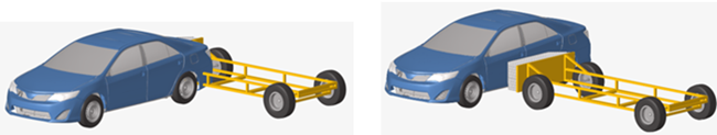
Figure 1.
-
From the Safety ribbon, click the Barrier
Positioner tool.

Figure 2. -
On the guide bar, click
 to open the hamburger menu to
select the regulation, load case and barrier position options.
to open the hamburger menu to
select the regulation, load case and barrier position options.
- Load Case: Select Front, Side or Rear.
- Regulation: Select the regulation for the selected load case.
- Barrier Front Foam Distance: The search distance, from the barrier frontal face, used to automatically identify the barrier foam blocks.
- Vehicle Front Axis: The orientation of the vehicle.
- Barrier Front Axis: The initial orientation of the barrier.
- Overlap (in % age): The lateral overlap between barrier and vehicle for frontal and rear impacts.
- Lateral angle: The rotation angle of the barrier for frontal OMDB.
- IRD/R-Point offset distance: The IRD or offset distance to use for the positioning for side impacts. When the value is equal to 0.0, the IRD or offset distance is automatically computed as per the regulation.
- Barrier Height From Ground: The height of the barrier frontal zone above the ground, as per the regulation.
- Vehicle To Barrier Distance: The offset between the vehicle and the barrier.
-
Select the barrier components.
It is recommended to use the advanced selections (
 )
and filter “by include” and directly select the barrier include file.
)
and filter “by include” and directly select the barrier include file. Once the barrier components are selected, all of the other displaced components are automatically selected as vehicle components.
Once vehicle components are identified, a microdialog opens.
-
Select the relevant inputs needed for the selected regulation in the microdialog.
For example, for Euro-NCAP Side Impact, the following microdialog opens, where selections for Base Node and Inclination Node define the ground position, and RPoint is provided.
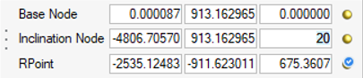
Figure 3.