Overview of the point connector realization process and methods.
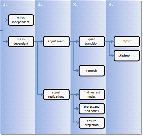
The following flow chart outlines a four-stage process used to select the best
routine for point realizations. Figure 1.
Under the Connectivity heading, select the realization type.
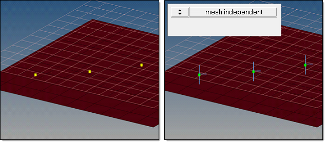
mesh independent
Use for realizations that do not need mesh changes for the body of
the realization, and the connection is primarily defined via a
solver-specific card or 0D elements, such as CWELDs for Nastran or ACM for OptiStruct.
During the realization, the solver-specific connection is created.
For example, for the Nastran CWELD of
ELEMID option, the shells which are in contact are observed and
defined in the CWELD card.
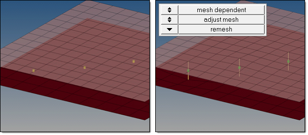
mesh dependent
Use for all other cases.
If mesh dependent is selected, you must decided whether
to adjust the mesh or the realization.
adjust mesh
Projection is done in a perpendicular way, and the mesh must be
adapted to the projection points.
adjust realizations
The mesh will not be modified, at the expense of non-normal or
incomplete realizations. Many realization types are defined with
head elements attached to body elements. In the case of these
realization types, the head elements realize the connection without
modifying the mesh. Then the body element is still created in a
normal direction.
Select a method for performing adjustments.
Adjust Mesh
remesh
Takes the projection points into account and uses snap
and split capabilities to connect the weld to the
links.
quad transition
Creates perfectly shaped quad elements around the
projection points. By default, the quad size is
determined by the average mesh size. Alternatively, you
can specify a specific quad size in the Quad Size
field.
For point quad transition, the automatic snapping and
feature detection option, Allow
Snapping, is activated. This prevents
the creation of elements that are too small and ensures
that the geometry is not modified too much.
Free edges and features with an angle greater than 25°
are always taken into account. If smaller feature angles
should be considered, decrease the value in the Feature
Angle field under the Behavior heading. Feature angles
smaller than 5° will not be considered at all.
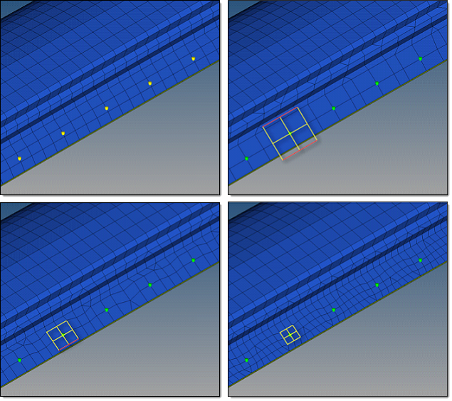
By default, snapping is allowed by a distance of one
third of the quad pattern element size. In the case of a
predefined quad pattern element size of 10.0, the outer
nodes can snap to features in a distance of 3.3. The
algorithm also tries to snap all three nodes of a quad
pattern or none. The top, left image illustrates the initial
model situation. The remaining images illustrate
connectors that have been realized with quad
transition using different quad pattern sizes:
average, coarse, small. The regular quad pattern
size is highlighted and the red lines illustrate
which nodes have been snapped to a relevant
feature or free edge.
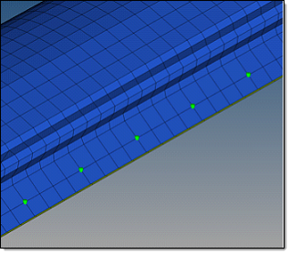
The image below is the same example as above, except the
model is realized as a quad transition with an adequate
quad pattern size.
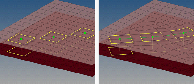
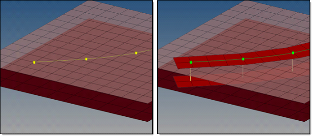
In Figure 2, points were created at the same
exact position, though there is a notable difference. In
both images, the connectors have been created along a
line, but in the left image the split to
points option was enabled.
Therefore, in the left image, the quad transition
pattern is aligned to the mesh; in the right image, the
quad transition pattern is oriented along the point
connector line. All elements around the point connector
line belong to the regular pattern. The number of
element pairs created along the point connector line
between the point positions depends on the average or
selected mesh size, which can range from one to many.
The quad elements are distributed equidistant along the
line.
In curved regions the inner and outer lengths of the
element edges differ. Figure 2.
Adjust Realizations
find nearest nodes
Only searches for the nearest nodes within the given
tolerance, making it possible to connect t-joints and
similar areas. This option is very useful in situations
where the connectors are not positioned perfectly. The
realizations are allowed to be non-normal.
Find nearest node does not perform projections. Figure 3.
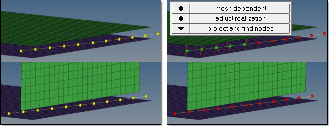
project and find nodes
Requires a valid normal projection onto the link
entities in a first step. In a second step, the nodes
closest to the projection points will be used for the
connection. If a normal projection is not possible, the
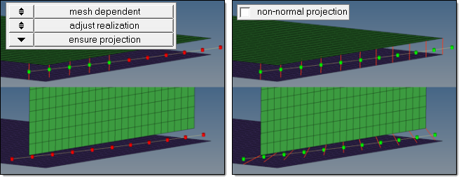
realization fails as indicated in the image below. Figure 4.
An angle of less than five degrees is considered normal.
Activating the Nonnormal checkbox
under the Behavior heading omits the requirement for a
normal projection and permits links to only be found in
the connector tolerance. The result is exactly the same
as it is for the find nearest
nodes option. Figure 5.
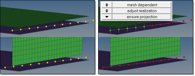
ensure projection
The minimum condition for the realization is a possible
projection. The realization will be performed in the
direction from one projection point to the next. If the
projection point is coincident with a shell node they
will be equivalenced. Figure 6.
Note: Ensure projection can lead to incompletely defined
connections from a solver perspective unless the
connector positions are not aligned to the mesh. The
advantage of this projection method is the exact
determination of the projection points.
Enabling the Nonnormal checkbox allows the
realization to be performed from one projection point to the
next. Figure 7.
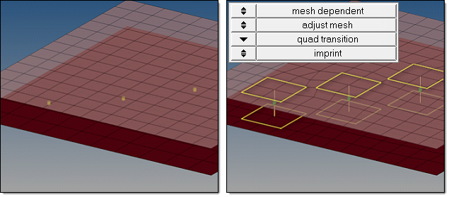
If you selected quad transition in step 3, you must
select whether to imprint or skip imprint.
imprint
When creating mesh-dependent realizations with quad transitions, the
quad transition meshes can overlap and disturb each other if more
than one set of connectors is created too close to each other.
Imprint reconcile such transitions with each other and modifies the
underlying mesh to match the results. This creates a final result
that is seamless and properly meshed.
The option Resolve Conflicts is activated by
default, enabling smaller imprint conflicts to be automatically
resolved when connectors are realized. Overlapping elements are
released, and a normal remesh of that area is performed as long as
the overlapping area is smaller than half the regular quad
transition element size. Figure 8.
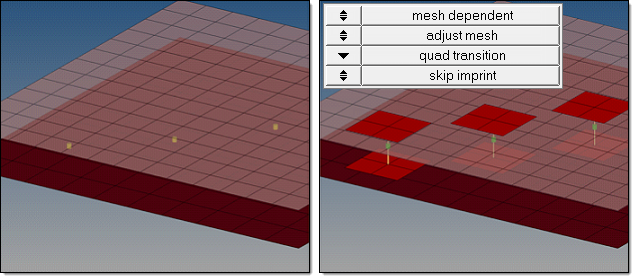
skip imprint
Prevents the last step of quad transition from being performed. The
component ^conn_imprint is created instead, which contains the
element pattern. These elements can be modified and manually
imprinted later using the Connector Imprint panel.
Skip imprint allows you to realize such mesh-dependent realizations
in very complex areas of the model where the automatic imprint fails
because of issues such as conflicting points.