Ply Geometry Smoothing provides functionality to smooth finite element ply shapes,
usually generated from concept level composite freesize optimization, and to generate
geometry from finite element ply shapes.
From the menu bar, click Aerospace > Composites > Ply Geometry Smoothing.
Select the FE ply to be converted into geometry shape.
Choose the location where geometry should be placed.
Original component
Separate component for each ply
Select either line or surfaces geometry to be exported as step files.
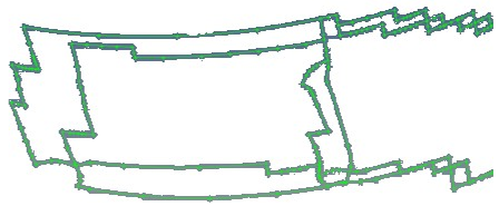
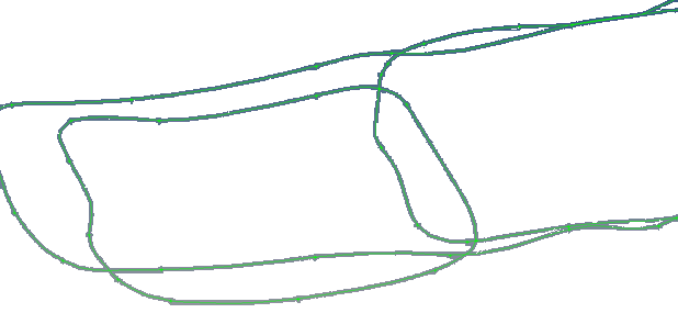
Set Smooth Iteration to zero if the exact shape is to be preserved without
smoothing the boundary. Otherwise, use 10-20 for the iteration.
If you would like to define small holes to be filled, patched, or removed from
the ply, set small region to one of the following:
Area Ratio – ratio of small region area to laminate area
Element Count – number of elements that define the small region
To generate new plies if the input ply is made up of multiple separate regions,
select Split disconnected ply regions into separate new ply
entities.
Update ply element sets by selecting one of the following:
Unchecked – generates requested geometry for ply but does not change
element set assigned to input ply.
Checked – in addition to generating requested geometry, a new element
set that reflects smoothing is created and assigned to input ply.
Provide the step file name.
Geometry plies are created and exported to step files. Figure 1. Result of Smoothing with Iterations = 0 Figure 2. Result of Smoothing with Iterations = 20